


6.9 Curtain walling and cladding
| 6.9 - Appendix 6.9A | ||
| Interfaces | ||
Appendix 6.9-A
Interfaces
Interfaces exist:
- between different curtain walling and cladding systems, and
- between curtain walling and cladding systems and other elements of the building.
All interfaces should be carefully designed and detailed to resist water and wind penetration. External and internal air and water seals should normally be provided.
The design should take account of:
- differing profile characteristics
- movement
- continuity of insulation, vapour barriers and breather membranes
- tolerances and deviation
- the erection sequence
- planned maintenance.
The drawings and specification should indicate clearly which contractor is responsible for constructing the interface.
Typical interfaces
The following sketches show examples of typical interfaces and illustrate general design principles.
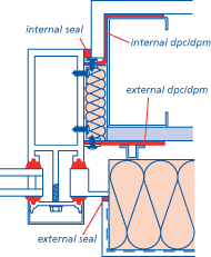
1. Curtain walling to insulated render system
Horizontal section
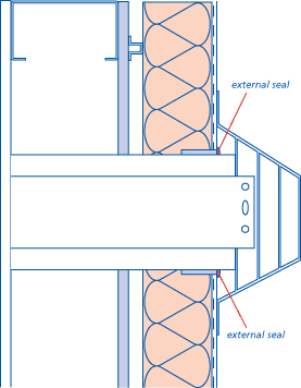
2. Curtain walling to balcony/terrace
Vertical section
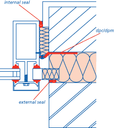
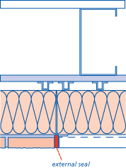
3. Curtain walling to conventional brick & block wall
Horizontal section
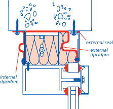
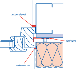
4. Curtain walling to soffit
Vertical section
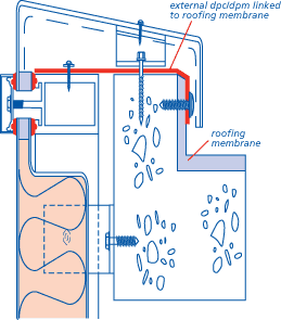
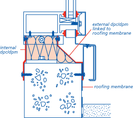
5. Curtain walling to roof including coping detail
Vertical section
6. Brick slip cladding to insulated render system
Horizontal section
7. Insulated render system to windows & doors
Horizontal section
8. Penetration of gas flue through insulated render system on light gauge steel frame
Horizontal section

