


6.2 External timber framed walls
SCOPE
DESIGN STANDARDS
Dwellings with a timber frame superstructure require certification indicating that the design has been checked by an NHBC timber frame certifier. See Appendix 6.2-A.
Design that follows the guidance below will be acceptable for external walls of timber framed dwellings, substantially timber framed dwellings and wall panels. This Chapter applies to timber framed walls up to seven storeys high.
For guidance on the prevention of fire during construction see 'Fire prevention on construction sites' jointly published by the Construction Confederation and the Fire Protection Association (www.thefpa.co.uk).
STATUTORY REQUIREMENTS
Design should be in accordance with relevant Building Regulations and other statutory requirements.
LOADBEARING WALLS
Structural design of loadbearing timber framed walls should be in accordance with BS EN 1995-1-1. The design should take into account:
- wind loads
- roof loads
- floor loads.
Items to be taken into account include:
All structural timber should be:
- of a suitable grade in accordance with BS EN 338 and BS EN 14081-1
- dry graded and marked in accordance with BS 4978.
Sheathing and its associated fixings should be structurally adequate to resist racking due to wind and other forces.
Individual studs should be not less than 37mm wide, at maximum 600mm centres, unless other adequate support is provided for wall boards and fixings.
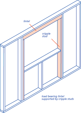
A lintel and cripple studs should be provided to any opening in load-bearing panels except when the opening does not affect the stud spacing or where the supported loads are carried by a rim beam or perimeter joist.
Additional studs may be required at openings for fixing wall ties where masonry cladding is used.
Multiple studs should be included to support multiple joists and other point loads unless otherwise specified by the designer.
The design should avoid narrow, inaccessible gaps between studs which are difficult to insulate.
Wall panels should be adequately fixed to the sole plate which in turn should be anchored to the substructure to resist all the lateral and vertical forces acting at these junctions. Typical details are shown in Clause S2.
Where frames are fixed to masonry or beam and block floors by shotfiring, the blocks should be concrete blocks to BS EN 771 with a minimum crushing strength of 7.3N/mm2. Blocks in beam and block floors should be grouted.
Wall panels should be securely fixed together and fixed to floor and roof framing where appropriate. Appropriate measures should be taken to prevent buckling.
If head binders are not provided joists and roof trusses, including girder trusses and other similar loads, should bear directly over studs.
At joints between wall panels, sole plates and head binders should be provided to bind panels together. Joints in sole plates and head binder should not coincide with those between panels. Joints in head binders should occur over a stud.
MOISTURE CONTROL AND INSULATION
Items to be taken into account include:
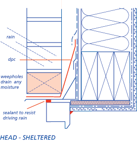
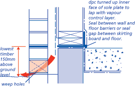
Dpcs should be installed below the sole plates of all ground floor walls, including internal partitions, to protect timber from rising damp and residual construction moisture.
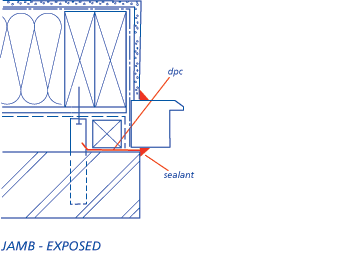
Dpcs and trays should be fitted at openings where needed to prevent rain penetration.
In Scotland, Northern Ireland, the Isle of Man and other places where the exposure to driving rain is Severe or Very Severe, masonry should form a rebate at the reveals of openings to avoid a straight through joint where the frame abuts the masonry.
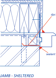
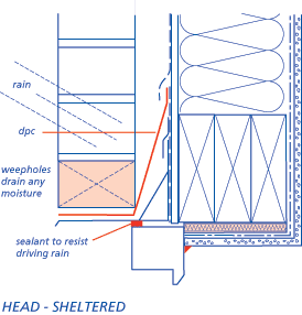
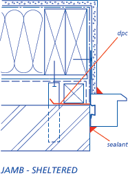
Breather membranes should be lapped so that each joint is protected and moisture drains outwards and downwards as shown in Clause S3.
In areas of Very Severe exposure to wind driven rain (as defined in Appendix 6.1-A) a high performance breather membrane should be used (unless the alternatives given in Clause D4(c) below are adopted).
A drained and vented cavity should be provided to reduce the risk of rain penetrating to the frame. The following minimum cavity widths, measured between the cladding and sheathing, should be provided:
| Cladding | Minimum cavity width |
| Masonry | 50mm nominal |
| Render on backed lathing |
25mm nominal |
| Vertical tile hanging without underlay |
No vertical cavity required when a breather membrane is fitted to the sheathing |
| Other cladding* | 15mm |
* See Chapter 6.9 'Curtain walling and cladding'.
In areas of Very Severe exposure to wind driven rain (as defined in Appendix 6.1-A) the wall construction should include a 50mm cavity between the sheathing and the cladding and:
- a high performance breather membrane, or
- a masonry cladding which is rendered or clad with an impervious material.
The cavity should be extended at least 150mm below dpc, to allow drainage of the cavity and should be kept clear. Open brick perpends should be provided where necessary to prevent water build up in the cavity. These openings can also provide cavity venting.
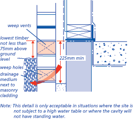
The cavity should be vented to allow some limited, but not necessarily through, movement of air. Where wall areas are divided by horizontal cavity barriers and openings should be provided to each section (see Clause 6.2 - D7).
The openings should be:
- equivalent to open brick perpends every 1.2m
- located to prevent the ingress of rain,
or - below the lowest timber.
Proprietary perpend ventilators are available.
These openings can also provide drainage of the cavity.
The BRE Report 'Thermal insulation: avoiding risks' discusses aspects of insulation relevant to external timber framed walls. In England and Wales account should be taken of Accredited Details.
Insulation should normally be placed within the stud void. Partial fill cavity insulation, with a 50mm residual cavity, between it and any cladding may be needed but should be assessed in accordance with Technical Requirement R3 as an integral part of the wall system and installed in accordance with the assessment.
Insulated sheathing boards should be assessed in accordance with Technical Requirement R3 and installed in accordance with the assessment.
Wall insulation should be of a type which 'breathes' eg, mineral wool (rock or glass). Other insulation materials should be assessed in accordance with Technical Requirement R3 for use in timber frame wall panels and installed in accordance with the assessment.
Water and heating services within walls should be on the warm side of the insulation.
A vapour control layer should be fixed on the warm side of the wall insulation.
The vapour control layer should cover the external wall including bottom rails, head rails, studs, lintels and window reveals.
Vapour control layers should be of 500 gauge (120 micron) polyethylene or vapour control plasterboard.
All joints in sheet vapour control layers should have at least 100mm laps and be located on studs or noggings and be adequately fixed to the frame.
PRESERVATIVE TREATMENT
Items to be taken into account include:
Timber framing should be treated in accordance with the guidance in Chapter 2.3 'Timber preservation (natural solid timber)', to which reference should be made.
I-studs manufactured from timber of durability class 'moderately durable' or lower should be preservative treated in accordance with Chapter 2.3 'Timber preservation (natural solid timber)'.
Timber cladding should be treated in accordance with the guidance in Chapter 2.3 'Timber preservation (natural solid timber)'.
EXTERIOR CLADDING
Items to be taken into account include:
A drained and vented cavity between exterior cladding and the sheathing should be specified as detailed in Clause D4. This cavity should not contain electricity cables other than meter tails.
Wall ties should be:
- of a type which complies with BS EN 845 and fully permits differential movement between the timber frame and the cladding - see Clause D6(c) below
- fixed to studs, not sheathing
- spaced at a maximum of 600mm horizontally and 450mm vertically
- spaced at jambs of openings and at movement joints in masonry a maximum of 300mm vertically within 225mm of the masonry reveal or movement joint. In this case additional studs may be needed
- spaced within 225mm of the top of a masonry wall
- inclined away from the sheathing so that the slope is maintained following differential movement.
Differential movement
During the first two years after erection, the timber frame will reduce in overall height as it dries out. The anticipated amount of shrinkage of the timber frame is given in Appendix 6.2-C.
Movement between the timber frame and other parts of the construction will occur at:
- door and window openings
- eaves and verges
- balconies (including Juliet balconies)
- openings for drive-throughs
- staircases and lift shaft enclosures (where they are not timber framed)
- service entries
- the interface of the timber frame with any other construction.
Appendix 6.2-C provides guidance on the anticipated amount of shrinkage of the timber frame and where it will occur between other parts of the structure. The extent of the differential movement increases with the number of storeys. Movement gaps should be filled with suitable materials to take up the expected movement. The manufacturer of the material should be consulted on the suitability for the extent of the movement expected.
Where the movement gap is expected to be more than 35mm it should be protected by a cover strip.
All claddings that are fixed direct to the timber frame, should have a horizontal movement joint at each floor level. See Appendix 6.2-C
Masonry claddings should not be supported by the timber frame.
Prefabricated chimneys should either be supported by:
- the masonry cladding, or
- the timber frame, including any roof construction supported by the timber frame.
Differential movement should be allowed for services both within the timber frame envelope or where they pass through it. Additional guidance is given in Appendix 6.2-C or in the case of gas services publications from the Institution of Gas Engineers and Managers (www.igem.org.uk).
CONTROL OF FIRE
Guidance on the prevention of fire during construction is given in 'Fire prevention on construction sites' jointly published by the Construction Confederation and the Fire Protection Association (www.thefpa.co.uk).
All elements should have adequate fire resistance.
Service mains should not pass through separating wall cavities.
In Scotland services are not permitted within a timber framed separating wall.
Service outlets should not impair the fire resistance of floors and walls.
Items to be taken into account include:
The design should detail the position and materials for cavity barriers in accordance with relevant Building Regulations.
Horizontal cavity barriers (except under eaves) should be protected with a dpc tray. The tray should have a minimum upstand of 100mm. Alternatively polyethylene encased cavity barriers providing a minimum upstand of 100mm should be used.
Dpcs should be used to cover horizontal and vertical cavity barriers and to shed moisture away from the sheathing. Typical details are shown in Clause S8.
Vertical timber cavity barriers should be protected from penetrating moisture by a dpc.
The design should detail the position and type of fire-stops in accordance with relevant Building Regulations.
A typical fire-stop detail is shown in Clause S8.
PROVISION OF INFORMATION
Ensure that design and specification information is issued to site supervisors and relevant specialist subcontractors and/or suppliers.
Where proprietary products are to be used, manufacturers usually have specific requirements for fixing and/or assembly of their products. This information should also be made available for reference on site so that work can be carried out satisfactorily in accordance with the design and specification.
The fixing schedule should allow for every structural connection made on site including fixing details for framing, wall ties, breather membrane, sheathing and vapour control layers, and should show as appropriate:
- number and spacing of nails and staples
- size and type of nail including material and corrosion protection
- method of nailing (eg skew, end, etc.).
Where the wall design relies on plasterboard to take racking forces those walls should be clearly defined and the type and centres of the fixings stated.
Copies of the fixing schedule should be given to the person doing the job.
The superstructure design should be placed with an NHBC approved timber frame certifier so that a certificate can be issued in accordance with Appendix 6.2-A.

