


DESIGN
Scope
This Chapter gives guidance on meeting the technical requirements and recommendations for low or zero carbon (LZC) technologies.
INTRODUCTION
This Chapter gives guidance on low or zero carbon (LZC) technologies acceptable to NHBC.
Other systems that follow the general principles of this Chapter may also be acceptable subject to specific agreement with NHBC.
Additional requirements for solid fuel and oil fired boilers are given in Chapter 6.8 ‘Fireplaces, chimneys and flues’. Guidance on other internal services is given in Chapter 8.1 ‘Internal services’.
The illustrations provided within the Introduction are generic and do not indicate the only possible systems acceptable to NHBC.
The LZC technologies covered in this Chapter include:
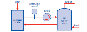
BIOMASS BOILERS
Biomass boilers burn wood pellets or wood chips for space and/or water heating.
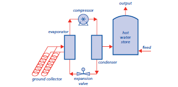
HEAT PUMPS
Heat pump systems provide space and/or water heating by transferring heat from a low temperature heat source. The most common heat sources are the ground, outdoor air or exhaust air
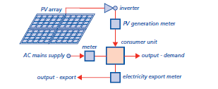
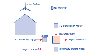
SOLAR PHOTOVOLTAICS
Solar Photovoltaic (PV) systems convert solar radiation into electricity
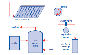
SOLAR THERMAL WATER HEATING
Solar thermal systems harness solar radiation for space and/or water heating.
WIND TURBINES
Wind turbine systems convert energy from the wind into electricity.
DEFINITIONS FOR THIS CHAPTER
Controls
Controls are used to operate and/or regulate the system and may be electrical or mechanical.
Exclusion zone
An area where entry is restricted during periods when maintenance is in progress, to prevent risk of injury or loss of life.
Fixing
A component which is used to attach the LZC technology to the structure.
Flashing
A piece of material, usually metal, plastic or composite, installed to prevent water from penetrating the building.
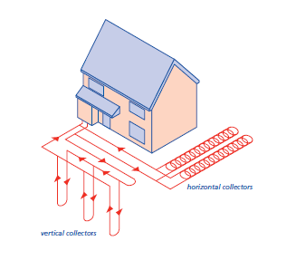
Ground collectors
The component of a ground source heat pump system which absorbs heat from the ground. Collectors can be installed either horizontally or vertically in the ground. They may also be incorporated into proprietary foundation systems.
Interface
Interconnection between two or more components.
Interstitial condensation
Condensation occurring within or between the layers of the building envelope.
Inverter
A device that convert direct current into alternating current.
Islanding (Island mode operation)
Where a LZC technology feeds the network or local distribution system during a planned or unscheduled loss of mains supply.
Low or zero carbon (LZC) technologies
A term applied to renewable sources of energy and also to technologies which are significantly more efficient than traditional solutions or which emit less carbon in providing heating, cooling or power.
Meter
Device that measures consumption and/or generation of energy.
Open loop system
A heat pump system that extracts water from an underground source, pumps it through a heat exchanger and returns it underground.
Parallel electrical generation
A system in which building loads can be fed simultaneously from the national grid or electricity supply grid and on-site sources such as wind turbines and photovoltaic panels.
Performance
The manner or quality of functioning for a material, product or system.
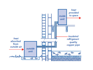
Refrigerant pipework
Carries refrigerant between the indoor and outdoor unit of a split system. Normally made of copper and must be insulated and protected from damage.
Renewable energy
Energy from naturally available sources that can be replenished including energy from the sun, the wind and tides, and from replaceable matter such as wood or other plant material.
Split system
A type of heat pump in which the condenser is located indoors, the evaporator is located outdoors, and the two are linked by refrigerant pipework.
Surface condensation
Condensation occurring on surfaces of the building.
Switchgear
The combination of electrical switches, fuses and/or circuit breakers used to isolate electrical equipment.
Vapour control layer
A material that restricts the passage of water vapour into the construction to reduce the risk of interstitial condensation.
DESIGN STANDARDS
Design that follows the guidance below will be acceptable for LZC technologies.
STATUTORY REQUIREMENTS
Design should be in accordance with relevant Building Regulations and other statutory requirements.
CERTIFICATION
LZC technologies should have current certification confirming satisfactory assessment by an independent technical approvals authority acceptable to NHBC.
System products and installations that are assessed and certificated through the Microgeneration Certification Scheme (MCS) will normally be acceptable to NHBC.
Further details of MCS can be found at:
www.microgenerationcertification.org
Other certification bodies or test documentation may be acceptable if they are considered by NHBC to be a suitable alternative.
When requested by NHBC the certification and relevant test documentation should be made available.
SYSTEM DESIGN
Items to be taken into account include:
(a) location
The output from certain LZC technologies may be affected by factors such as orientation, roof pitch, shading and geographical location.
For stand-alone wind turbine systems suitable exclusion zones should be provided in accordance with the manufacturer’s recommendations.
(b) systems
Each system should generally be supplied from one manufacturer as a package and not as individual components or materials. However, where components from more than one manufacturer are used they should be compatible to ensure satisfactory performance.
(c) performance
LZC technologies should be designed in accordance with the manufacturer’s recommendations and the certification scheme requirements and standards.
LZC technologies designed to contribute towards space and water heating should be designed in accordance with Chapter 8.1 ‘Internal services’ (Design).
(d) compatibility
Systems should be compatible with the building. Multiple systems should also be compatible with each other.
(e) acoustic performance
The design and location of LZC technologies should take account of internal and external noise and vibration.The effect on neighbouring properties should be considered, particularly the relative positioning of openings in relation to the LZC technology.
(f) drawings and specifications
Drawings and specifications should indicate clearly which manufacturer and/or installer is responsible for each system, including interfaces.
BUILDING INTEGRATION
3.1 - D5
Low or zero carbon technologies shall not adversely affect the stability or weather resistance of the building
Items to be taken into account include:
(a) structural integrity
The design of the structure to which the LZC technologies will be attached should take account of:
- the self–weight of the LZC components
- imposed loads
- wind loads
- snow loads
- dynamic loading (where relevant).
Foundations for stand-alone LZC technologies should be designed by an Engineer in accordance with Technical Requirement R5.
Where stand-alone systems are installed the foundations and anchor points should be designed to withstand the structural forces acting upon them.
Wind turbines should be designed in accordance with BS EN 61400.
(b) supporting structure
The structure to which the LZC technology is attached should be assessed to ensure that it is able to accept the design loadings and prevent detrimental effects arising from movement or vibration.
(c) fixings
Fixings, supports, bracketry and mounting frames should be designed to accommodate all static and dynamic loads in accordance with the manufacturer’s recommendations.
Fixings, supports, bracketry and mounting frames should be designed to take account of ventilation and drainage requirements of the LZC technology.
(d) weather resistance
The interface between the LZC technology and the building should be designed to ensure that moisture is prevented from reaching the interior, or any part of the structure that could be adversely affected by its presence.
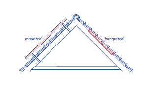
To ensure satisfactory performance, the interface of a roof or wall integrated system and the part of the roof covering or wall cladding it replaces should be weatherproofed by appropriate flashings and sealed to limit air leakage.
Weatherproofing details that rely solely on sealant are not acceptable.
(e) thermal bridging and condensation
To avoid the potential for surface and/or interstitial condensation, the design should take account of thermal bridging, particularly where any part of the system, including fixings, penetrates the thermal envelope of the building.
(f) corrosion protection
Metalwork used for fixings, supports, bracketry or mounting frames should have adequate protection against corrosion.
Where two metals are to be joined they should be compatible or isolated from each other to prevent bimetallic corrosion.
Aluminium and aluminium alloys should not come into contact with cementitious material.
ELECTRICAL REQUIREMENTS
The electrical installation should comply with BS 7671 ‘Requirements for Electrical Installations’.
Where parallel electrical generation occurs, inverters should have a current Engineering Recommendation G83/1 Type Test certificate and comply with all other parts of ER G83/1 for standard installations. Larger installations should comply with ER G59/2.
The electrical installation should be capable of being isolated from all other electrical sources when required for maintenance or testing.
LZC technologies which generate electricty and are connected to the mains should automatically disconnect when there is a mains power failure. This is to prevent them from feeding the network or local distribution system during a planned or unscheduled loss of mains supply. This is known as ‘islanding’.
DISCHARGE
Discharge from solar thermal water heating systems should be into a storage vessel. The vessel and discharge pipework should be suitable to withstand high temperatures.
All air source systems should incorporate an automatic defrost cycle and suitable condensate drainage.
INSULATION OF PIPEWORK
Where there is a risk of pipes freezing, they should be insulated, particularly when at, or close to, ground level.
GROUND COLLECTORS
Excavations for the installation of ground collectors should not adversely affect aquifers, foundations, drainage, water supply pipes and other services. Design should take account of local planning authority guidance including where excavations are close to trees and hedgerows (see Chapter 4.2 ‘Building near trees’).
The design of ground collectors should specify their depth and layout to avoid freezing of adjacent ground.
Where open loop systems are proposed, consultation with the Environment Agency, Northern Ireland Environment Agency or Scottish Environment Protection Agency, as appropriate, should be made.
Open loop systems may require one or more of the following:
- a licence to investigate groundwater
- an abstraction licence
- a discharge consent.
REFRIGERANT PIPEWORK
Refrigerant pipework connecting split systems should be of refrigerant quality copper pipe or other material as recommended by the manufacturer. The pipe should be insulated and the insulation should incorporate a vapour control layer to prevent ice build-up.
FUEL STORAGE
3.1 - D11
Fuel storage for biomass boilers shall be suitable for the installation
The location of fuel storage should take account of access for delivery.
Fuel stores should:
- be of a suitable size to take account of peak load and period of demand
- have fire detection and extinguishing equipment where elevated dust levels are expected
- have appropriate fire resistance and separation to prevent fire and gases entering other parts of the building, where they are integral.
Guidance is given in The HVCA Guide to Good Practice Installation of Biofuel Heating (TR/38).
CLEAN AIR ACT
Biomass boilers that are to be installed within a smoke controlled area should comply with the Clean Air Act 1993 or Clean Air (Northern Ireland) Order 1981.
ACCESS
Design should take account of safe access to the LZC technologies, including switchgear, inverters, meters and controls, for cleaning, inspection, maintenance and repair of systems.
PROVISION OF INFORMATION
Designs and specifications should include:
- Designs and specifications should include:
- full set of current drawings
- manufacturers’ specifications
- fixing schedule
- interfaces
- controls
- on-site testing
- commissioning schedule.
Designs and specifications should be issued to consultants, relevant specialist subcontractors, site supervisors and/or suppliers as appropriate.

