


7.1 Flat roofs and balconies
Appendix 7.1-A
Commonly used flat roofs
Three types of flat roof are shown here to illustrate the principles of their design:
| WARM ROOF (insulation on top of deck) | ||
| concrete deck | timber deck | profiled metal deck |
 |
 |
 |
| * mineral surfaced or solar reflective treatment where required | ||
| INVERTED WARM ROOF (insulation on top of waterproofing) |
| concrete deck |
 |
| GREEN ROOF | |
| intensive (requires regular maintenance. Plants contained within soil) | extensive (requires periodic maintenance. Plants generally contained in the sedum blanket |
 |
 |
WARM ROOF (concrete deck)
Surface treatment
See Appendix 7.1-B
Waterproofing and insulation
Waterproofing should be one of the following:
- reinforced bitumen membrane (RBM) to BS 8747 from the following table:
| Type of Reinforced Bitumen Membrane (RBM) | Insulation material | Method of fixing first layer | ||
| First/preparatory layer | Second layer/underlay | Final layer/cap sheet | ||
| Type 3G perforated layer | S2P3 | S5P5 with either integral mineral finish or separate solar protection | Rigid Urethane Foam (RUF) boards (polyurethane (PU) and polyisocyanurate (PIR) | Loose laid and lapped, to produce partial bonding. |
| Type 3G perforated layer | Elastomeric underlay achieving S2P3 | Elastomeric capsheet achieving S5P5 | ||
| S2P3 fully bonded | S2P3 | S5P5 with either integral mineral finish or separate solar protection | Compressed cork, rock fibre or glass fibre boards, cellular glass slabs, perlite boards, or composite products | Full bitumen bonding, per BS 8217 |
| S2P3 fully bonded | Elastomeric underlay achieving S2P3 | Elastomeric capsheet achieving S5P5 | ||
| Note: torching onto insulation boards, except rock/glass fibre or perlite is not acceptable. Note: Elastomeric (i.e. SBS polymer-modified) bitumen membranes, with greater extensibility and flexibility, especially at low temperatures, are likely to provide longer service life. |
||||
- mastic asphalt, 20mm thick on the flat, laid in two layers, all to BS 8218 onto black sheathing felt
- a thermoplastic single ply membrane, assessed in accordance with Technical Requirement R3, either bonded to the insulation, mechanically fixed to the deck through the insulation, or loose-laid, sealed and ballasted. Refer to the manufacturer's instructions for details.
Vapour control layer
The vapour control layer should consist of at least one layer of bitumen roofing membrane (S2P3) fully bonded to the structural deck and all laps sealed with bitumen.
Concrete deck and screed
Concrete roof deck, suitably primed, with sand/cement screed topping to achieve the falls. The screed should be in accordance with Clause 7.1-S7(a).
Detailing
Typical details are shown in Appendix 7.1-C.
WARM ROOF (timber deck)
WARM ROOF (profiled metal deck)
Surface treatment
See Appendix 7.1-B
Waterproofing and insulation
Waterproofing should be one of the following:
- reinforced bitumen membranes (roofing felt) to BS 8747 from the following table:
| Type of Reinforced Bitumen Membrane (RBM) | Insulation material | Method of fixing first layer | ||
| First/preparatory layer | Second layer/underlay | Final layer/cap sheet | ||
| Type 3G perforated layer | S2P3 | S5P5 with either integral mineral finish or separate solar protection | Rigid Urethane Foam (RUF) boards (polyurethane (PU) and polyisocyanurate (PIR) | Loose laid and lapped, to produce partial bonding |
| Type 3G perforated layer | Elastomeric underlay achieving S2P3 | Elastomeric capsheet achieving S2P3 | ||
| S2P3 fully bonded | S2P3 | S5P5 with either integral mineral finish or separate solar protection | Compressed cork, rock fibre or glass fibre boards, cellular glass slabs, perlite boards, or composite products | Full bitumen bonding, per BS 8217 |
| S2P3 fully bonded | Elastomeric underlay achieving S2P3 | Elastomeric capsheet achieving S2P3 | ||
| Note: torching onto insulation boards, except rock/glass fibre or perlite is not acceptable. Note: Elastomeric (i.e. SBS polymer-modified) bitumen membranes, with greater extensibility and flexibility, especially at low temperatures, are likely to provide longer service life. |
||||
- mastic asphalt, 20mm thick on the flat, laid in two layers, all to BS 8218 onto black sheathing felt
- a thermoplastic single ply membrane, assessed in accordance with Technical Requirement R3, either bonded to the insulation, mechanically fixed to the deck through the insulation, or loose-laid, sealed and ballasted. Refer to the manufacturer's instructions for details.
Vapour control layer
In bonded systems the vapour control layer should consist of at least one layer of bitumen roofing membrane (S2P3) fully bonded or nailed to the structural deck and all laps sealed with bitumen. In mechanically fixed systems the vapour control layer should consist of suitable polyethylene sheet sealed at all laps.
Preservative treatment
All roof timbers, joists, wall plates, blocking, strutting, battens, firrings, noggings to be preservative treated, unless naturally durable. Chapter 2.3 'Timber preservation (natural solid timber)' gives details of preservative treatments.
Deck
Timber or timber-based decks should be one of the following:
| Material | Thickness of deck (mm) | |
| Joist centres (mm) | ||
| 450mm | 600mm | |
| Pre-treated plywood, WBP grade | 15 | 18 |
| Marine plywood, WBP grade | 15 | 18 |
| Oriented Strand board Type OSB3 | 15 | 18 |
| Pre-treated timber planking - tongue and grooved ('close boarded timber') Max. board width 100mm. | 19 | 19 |
Reference should be made to Sitework clause 7.1 - S6 for fixing of the deck to joists.
Joists
For sizes and spacing, reference should be made to appropriate load/span tabales published by TRADA in support of Building Regulations and associated documents.
Detailing
Typical details are shown in Appendix 7.1-C.
INVERTED WARM ROOF(concrete deck)
(NOT suitable for slopes greater than 10°)
Ballast
Ballast should consist of paving slabs, or of rounded pebbles of minimum diameter 19mm to the depth specified in the design.
Filter layer
Geo-textile layer, laid over insulation boards to prevent fines from reaching the membrane surface.
Insulation
Insulation should be of a type unaffected by exposure to the weather and capable of supporting the weight of the ballast. Only the following materials are suitable:
- extruded polystyrene (XPS)
- extruded polystyrene, with cementitious surface.
Waterproofing
Waterproofing should be one of the following:
- reinforced bitumen membranes (roofing felt) to BS 8747 from the following table:
| Type of Reinforced Bitumen Membrane (RBM) | Deck material | Method of fixing first layer | ||
| First/preparatory layer | Second layer/underlay | Final layer/cap sheet | ||
| Type 3G perforated layer | S2P3 | S5P5 with either integral mineral finish or separate solar protection | Concrete, or concrete with sand/cement screed | Loose laid and lapped, to produce partial bonding |
| Type 3G perforated layer | Elastomeric underlay achieving S2P3 | Elastomeric capsheet achieving S2P3 Mineral surfaced on exposed upstands, etc. | ||
| Note: Concrete or screeded substrates should be adequately dry to receive waterproofing system Note: Elastomeric (i.e. SBS polymer-modified) bitumen membranes, with greater extensibility and flexibility, especially at low temperatures, are likely to provide longer service life |
||||
- mastic asphalt, 20mm thick on the flat, laid in two layers, all to BS 8218 onto black sheathing felt.
- a thermoplastic single ply membrane, assessed in accordance with Technical Requirement R3, either bonded or mechanically fixed to the deck, or loose-laid, sealed and ballasted. Refer to manufacturer's instructions for details.
Concrete deck and screed
Concrete roof deck, suitably primed, with sand/cement screed topping to achieve the falls. The screed should be in accordance with Clause 7.1-S7(a).
Detailing
Typical details are shown in Appendix 7.1-C.
Note:
Inverted roofs should only be used with timber (solid or I-joist) or metal profiled decks if they have been designed to support the loads, particularly from the depth of ballast needed to retain the insulation material.
Green Roof
A green roof, either intensive or extensive, should be a complete system from the membrane manufacturer and not individual components or materials. The details given below are intended to be a guide and may vary depending on the individual manufacturers system.
The following identifies the two types of green roof:
Intensive Green Roof
| Feature | requires regular “intensive” maintenance e.g. similar to a normal garden provides a normal garden environment uses natural topsoil at least 150mm deep and normal plants |
| Structure | roof design to allow for full weight of wet soil 20° maximum roof pitch |
| Falls and moisture control |
drainage falls 1:60min irrigation system may be required to support plants in dry spells |
| Vapour control layer |
Fully bonded polyester-reinforced RBM (S2P3) |
| Insulation |
Insulation material to have adequate compressive strength to withstand likely applied loads Where the insulation is above the weatherproofing, only extruded polystyrene (XPS) should be used |
| Waterproofing | See separate table. A root resistant element such as a copper foil or “Preventol” treatment is required above the waterproofing membrane |
| Protection and filter layers |
A filter layer and protection layer (or board), above the waterproofing membrane, is required to prevent damage. These to be in accordance with the manufacturer’s recommendations |
| Type of Reinforced Bitumen Membrane (RBM) |
Insulation Material |
Method of fixing first layer |
||
| First/ preparatory layer |
Second layer/ underlay |
Final layer/ cap sheet |
||
| Type 3G perforated layer |
S2P3 | S5P5 with either integral mineral finish or separate solar protection | Rigid Urethane Foam (RUF) boards (polyurethane (PU) and polyisocyanurate (PIR)) |
Loose laid and lapped, to produce partial bonding. |
| Type 3G perforated layer |
Elastomeric underlay achieving S2P3 |
Elastomeric capsheet achieving S2P3 Mineral surfaced on exposed upstands, etc. |
||
| S2P3 fully bonded | S2P3 | S5P5 with either integral mineral finish or separate solar protection | Compressed cork, rock fibre or glass fibre boards, cellular glass slabs, perlite boards, or composite products |
Full bitumen bonding, per BS 8217 |
| S2P3 fully bonded |
Elastomeric underlay achieving S2P3 |
Elastomeric capsheet achieving S2P3 Mineral surfaced on exposed upstands, etc. |
||
| Note: torching onto insulation boards, except rockwool or perlite is not acceptable. Note: Elastomeric (i.e. SBS polymer-modified) bitumen membranes, with greater extensibility and flexibility, especially at low temperatures, are likely to provide longer service life. |
||||
| Mastic Asphalt Mastic asphalt to BS 8218. Three coat horizontally (30mm total thickness), two coat vertically (20mm total thickness). |
||||
Extensive Green Roof
| Features |
requires minimal maintenance e.g. annual attention a sedum blanket contains the plants |
| Structure | roof loadings less than Intensive roof |
| Falls and moisture control |
45° maximum roof pitch
|
| Vapour control layer |
Fully bonded polyester-reinforced RBM (S2P3) |
| Insulation |
Insulation material to have adequate compressive strength to withstand likely applied loads Where the insulation is above the weatherproofing, only extruded polystyrene (XPS) should be used |
| Waterproofing | See separate table. A root resistant element such as a copper foil or “Preventol” treatment is required above the waterproofing membrane |
| Protection and filter layers |
A filter layer and protection layer (or board), above the waterproofing membrane, is required to prevent damage. These to be in accordance with the manufacturer’s recommendations |
Appendix 7.1-B
Surface treatments
| Maintenance only for roofs up to 10° | Access roof, walkway or terrace deck | Further information may be obtained from | |
| Reinforced Bitumen Membranes (RBM) |
|
|
Flat Roofing Alliance http://www.fra.org.uk/ |
| Mastic Asphalt |
|
|
Mastic Asphalt Council http://www.masticasphaltcouncil.co.uk/ |
| Thermoplastic Single Ply Membranes |
|
|
Single Ply Roofing Association http://www.spra.co.uk/ |
Notes
- Loose surface finishes should be prevented from being removed by weather and discharged into gutters and drain pipes. Chippings should be not less than 12.5mm limestone or white spar, not pea gravel.
- Cement/sand blinding should be laid on two layers of waterproof building paper or two layers of 1000 gauge polyethylene separating membrane. The slabs should be kept back 75mm at perimeters and a 25mm movement gap incorporated for every 9m2 of paving laid.
- Timber decking systems should only use compatible preservative treatments. The undersides of the bearers should have large, smooth contact areas, with no sharp edges or corners.
Appendix 7.1-C
Construction details for flat roofs and balconies
This Appendix contains common details for flat roofs and balconies. The following sketches show examples of typical common construction details and illustrate general principles. Further information on specific waterproofing systems may be obtained from BS 8217 'Reinforced bitumen membranes for roofing - Code of Practice', the Flat Roofing Association, Mastic Asphalt Council or Single Ply Roofing Association.
CONCRETE DECK
Upstand
- upstand may be fixed to wall
- upstand to be at least 150mm high
- similar details apply to inverted roofs with concrete decks
Handrail fixing
- upstand should be formed in concrete roofs
Skirting to rooflight or ventilator kerb
- similar details apply to inverted roofs. Allow for thickness of ballast to achieve upstand dimension.
-
- Twin-kerb expansion joint expansion joint is similar for both warm and inverted concrete roofs.
TIMBER DECK
Mansard edge
- All elements should be firmly fixed to prevent peelback in high winds
Pitched roof abutment
Independent skirting detail
- upstands should be kept separate from wall - allow for movement
- upstand should be at least 150mm high
- similar details apply to cold deck timber roofs
Verge detail
- similar details apply to inverted deck
Welted drip to external gutter
- similar details apply to cold deck timber roofs
- inverted timber decks need special consideration to avoid insulation being lifted by wind suction. An alternative detail should be used.
Pipe passing through roof
- vapour control layer should be bonded to waterproofing
- detailing of upstand and flashing is similar for all roofs
Upstand to ventilator or rooflight kerb
- similar details apply to cold and inverted roofs. The thickness of ballast in inverted roofs, to achieve upstand dimensions, should be allowed for.
Rainwater outlet
- the opening should be properly trimmed
- the outlet should be at the lowest point in roof
- similar details apply to concrete roof
- ensure outlet is fixed securely to decking to prevent displacement by thermal expansion of rainwater pipe.
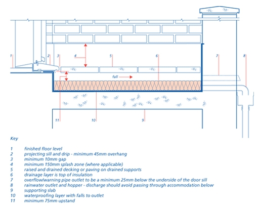
Appendix 7.1-D
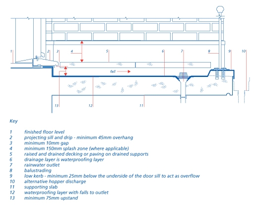
Balcony access,weatherproofing and drainage
This Appendix contains guidance on the principles to adopt for the weatherproofing and drainage of balconies which may then have an accessible threshold. Depending on the design, specific fire, thermal and acoustic issues may also need to be taken into account.
The design and construction of accessible balcony thresholds should incorporate all of the following:
The 15mm threshold upstand is measured at the door position. Additional sloping transition elements, such as a small internal ramp and external sill, may be provided either side of the upstand. The maximum slope on ramps and sills should be 15 degrees.
The sill should have a minimum 45mm overhang and drip to shed rainwater away from the interface between the waterproofing layer and the sill and to avoid reliance on exposed joint sealants and their limited design life.
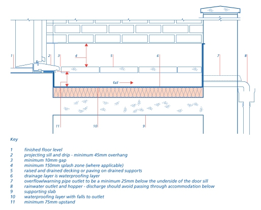
The balcony upstand is measured from the balcony drainage layer to the underside of the projecting sill. Note: the drainage layer may not be the waterproofing layer. For example, with an inverted roof the drainage layer would be the top of the insulation and not the waterproofing layer below. This is because drainage between the insulation and waterproofing layer could become silted resulting in the majority of rainwater flowing over the top of the insulation.
Finished falls should be a minimum 1:80 away from the building to the rainwater outlet(s). Where balconies are designed with falls toward or parallel to the building care must be taken to ensure any blockage of the outlet(s) cannot cause flooding into the building. Waterproofing layers at zero falls will only be accepted if the waterproofing membrane has a third party assessment specifically for that use. The membrane should also be fully protected from direct trafficking, for example by provision of paving slabs or decking, and be UV resistant unless fully protected from daylight. The membrane should be capable of withstanding any point loads from supports to decking or paving.
The drainage arrangement should ensure that if an outlet or downpipe becomes blocked it will not lead to flooding into the building. This can be achieved by using one outlet and an overflow (not less than the capacity of the outlet) or two outlets connected to independent downpipes. Alternatively, the balcony kerb can be set a minimum 25mm below the level of the door threshold to allow safe spillage in the event of water build up. An outlet chute through perimeter construction into external hoppers can also act as the overflow if it is of an appropriate size to serve both the discharge and overflow capacities.
Drainage gaps between individual lengths of decking or between each paving slab should be a minimum of 10mm. A similar continuous drainage gap should be provided between decking or paving and the threshold sill, perimeter walls and kerbs. Spacers and supports to raised decking or paving should not obstruct the flow of rainwater to outlet(s). The position of drainage outlets beneath decking or paving should be clearly identifiable and accessible for maintenance.
The design of the wall for minimum 150mm above decking or paving should ensure that any splashing off the decking or paving does not reach any part of the wall that could be adversley affected by the presence of moisture. This may be achieved by the use of an impervious wall finish/cladding or an extension of the balcony waterproofing layer to form an upstand with cover flashings and cavity trays if required.
Inverted balcony
Warm deck balcony
Cantilevered balcony