


6.1 External masonry walls
SITEWORK STANDARDS
Sitework that complies with the design and the guidance below will be acceptable for external masonry walls.
CONSTRUCTION
Items to be taken into account include:
(a) appearance
The appearance of a masonry wall depends upon the materials used, the setting out and the workmanship. Further details are given in Clauses S2 to S10.
(b) setting out
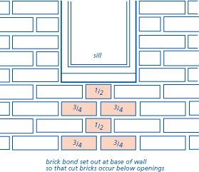
When setting out masonry, avoid cutting bricks or blocks except when it is essential and avoid irregular or broken bonds, particularly at openings.
Where a number of openings of similar width are being formed, use a rod cut to the required size to check the width of openings as the work rises.
To keep courses to the correct height, use a gauge rod. The rod should be marked with the height of windows, doors and floors.
All work should be reasonably level and true. The bond detailed in the design should be used. Perpendicular joints should be kept in line and plumb. Courses should be kept level by using lines and spirit levels.
(c) mortar
Different types of bricks and blocks need different strength mortar mixes. Some parts of the building, such as below dpc, chimneys and copings, may need a different mix to the main walling. Make sure the mix is right for the job.
Recommended mortar mixes are given in Appendix 6.1-C.
Plant and banker boards should be kept clean. Mixers should be kept clean to operate efficiently. The mortar colour should be consistent.
Mortar which has started to set should not be re-tempered.
All bricks and blocks should be laid on a full bed of mortar and all perpends should be solidly filled.
Joints should be filled to reduce the risk of rain penetration and dampness in the wall. Solid mortar bedding and fully filled perpends are particularly important in exposed areas and where the cavity is to be fully filled with insulation.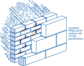
Unless the design states otherwise, only bucket handle or weathered joints should be used. Recessed joints should not be used where the cavity is to be fully filled with insulation.
Where pigments (to BS 1014) are used they should not exceed 10% of the cement weight or 3% if carbon black is used.
For precautions to take in cold weather, reference should be made to Chapter 1.4 'Cold weather working'.
(d) cavity walls
Cavities should be uniform and of the width specified in the design. All cavities should be at least 50mm nominal clear width. Partial cavity insulation should be fixed against the inner leaf of the cavity. Check that the correct wall tie is being used (reference should be made to Clause S5).
To keep the wall plumb, do not over-reach at changes of lift. It is better to wait for the next scaffolding lift.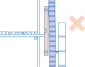
The difference in heights between the two leaves of a cavity wall under construction can be up to 6 block courses, provided the ties are sufficiently flexible to ensure coursing is achieved without breaking the bond.
Cavities should be constructed so that:
- mortar is struck off from all joints as work proceeds
- wall ties are kept free of droppings and debris
- cavity trays are clear of droppings and debris.
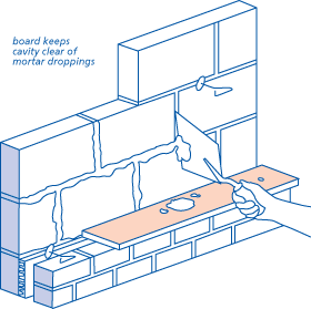
Clean cavities with mortar droppings removed are particularly important in exposed areas and where partial cavity fill is used.
Where cavity insulation is used, mortar droppings should be cleaned off from the top edge. Mortar left on the top edge may transmit dampness to the inner leaf. The use of a cavity batten will prevent this. Cavity battens should be wrapped with flexible material to allow easy withdrawal.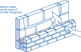
(e) movement
Brickwork/blockwork should not be subjected to vibration until the mortar has set.
(f) openings
Masonry may be built around either:
- the frame in-situ, or
- a profile or template to enable the frame to be fitted later.
Openings should be the correct size and square. The brickwork should butt closely against the frame. The frame should not be distorted by forcing bricks against the jamb.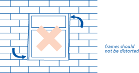
Window and door frames, when built-in, should be fixed with:
- frame cramps, or
- proprietary cavity closers, or
- plugs and fixings.
Timber plugs should not be used in vulnerable positions, such as the outer leaves of walls.
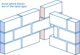
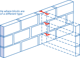
(g) bonding
A regular bonding pattern should be maintained. External walls should be bonded to partitions and party walls, as required by the design. Either:
- tooth every alternate course, or
- tie with wall ties, expanded metal or equivalent at centres not exceeding 300mm vertically.
Where joist hangers are not used, joist filling should be brick or blockwork, without excessive mortar joints. Clay bricks and concrete blocks should not be mixed. Joist filling should be kept 12mm below the top of flat roof joists to allow for timber shrinkage, but check also that cold roof ventilation is not blocked (reference should be made to Chapter 7.1 'Flat roofs and balconies' (Design and Sitework)).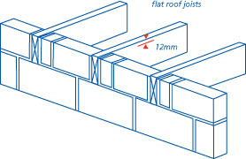
Where a different size of masonry unit is needed to ensure correct coursing, small units of the same material should be used to reduce cracking and problems due to different thermal insulation properties.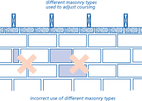
Where the inner leaf of a cavity wall is being used for thermal insulation and where a different size of masonry unit is used to ensure correct coursing, the unit should have similar thermal insulation properties to the masonry used for the rest of the wall. For example aerated concrete blocks should not be mixed with clay bricks.
(h) chasing for services
Chases should be cut with care. Impact power tools can damage the wall and should not be used.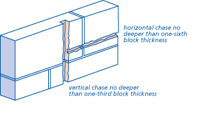
The depth for horizontal chases should be limited to one-sixth of the thickness of the single leaf. The depth for vertical chases should be limited to one-third of the thickness of the single leaf. Hollow blocks should not be chased unless specifically permitted by the manufacturer.
(i) movement joints
Movement joints should be formed where required by the design. Movement joints are necessary in long lengths of walling to reduce unsightly cracking. Joints are often hidden in corners, or behind rainwater pipes.
The correct materials should be used to form movement joints. Clay bricks expand and require an easily compressible material.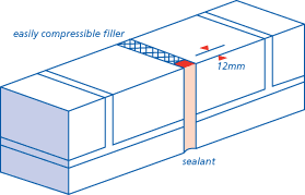
Suitable materials are:
- flexible cellular polyethylene
- cellular polyurethane
- foam rubber.
The sealant should be at least 10mm deep to ensure a good bond. If the joint is in a freestanding wall, the filler will require sealant to both exposed edges and the top (where the joint is carried through the coping).
(j) corbelling
Where courses are corbelled out in ordinary masonry, one above another, the extent of corbelling should not exceed that shown in the following diagrams.
Where reinforcing is used, corbels should be designed by an Engineer in accordance with Technical Requirement R5.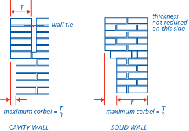
(k) calcium silicate bricks
Where calcium silicate bricks are used, the brick manufacturer's recommendations should be followed.
STONE MASONRY
Stone masonry will be acceptable if it:
- complies with brickwork/blockwork clauses (where appropriate)
- gives an adequate weather-resisting structure (in conjunction with any brick or block backing and/or vertical damp-proof membranes)
- is prepared and laid on its natural bed (unless local practice is otherwise)
- follows good local recognised practice.
DAMP-PROOF COURSES AND CAVITY TRAYS
Items to be taken into account include:
Dpcs and cavity trays should be in one continuous piece, whenever possible. Joints in horizontal wall dpcs positioned to prevent rising damp should be lapped 100mm or sealed or welded. The manufacturer's recommendations should be checked. Elsewhere, joints in dpcs and cavity trays should be sealed to prevent water seeping through the joints.
At ground level, all parts of the dpc should be at least 150mm above finished ground or paving level.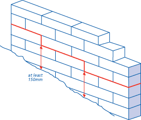
Special dpc detailing may be required at doorways where the dwelling is to be designed to allow access for the disabled.
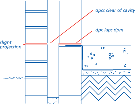
Dpcs should:
- be laid on a surface, free from projections which could puncture or adversely affect the dpc material
- be fully bedded on fresh mortar where required by the design, or where the building is over three storeys in height
- be of correct width
- not project into the cavity
- not be set back from the edge of the masonry
- lap the dpm.
The concrete fill in a cavity wall should stop at least 225mm below the base dpc. This may be reduced to 150mm where special foundations, such as rafts, are used.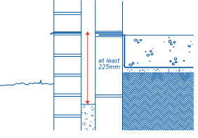
Parapet walls should have:
- a dpc under the coping, and
- a dpc tray starting 150mm minimum above the roof.
The coping throating should be clear of the brickwork. Reference should be made to Clause S4(d) for guidance on sealing dpcs.
All dpcs should be fully bedded in mortar.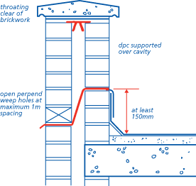
Where dpcs are intended to prevent the downward movement of water, joints should be sealed or welded. Lapped joints, unsealed, are unacceptable.
Where flashings link with dpcs, rake out 25mm of mortar below the dpc to allow for the flashing to be tucked in. It is easiest to rake out the joints as the work proceeds.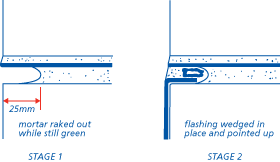
A dpc (either separate or combined as part of a proprietary cavity closer) should be provided at jambs of openings and at heads and sills as required by the design.
Where a jointed or permeable sill is used (all sills in Northern Ireland and the Isle of Man), a dpc should be placed between the sill and the outer leaf, turned up at the back and ends of the sill.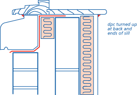
Where a separate vertical dpc is used it should be 150mm wide and be nailed to the full height of the frame. The dpc should protrude into the cavity by about 25mm and extend up to the underside of the lintel where it should be turned back towards the inner leaf.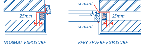
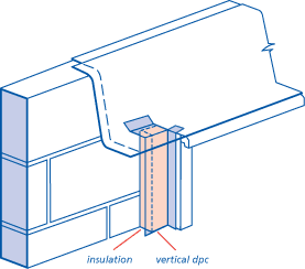
Where there is a sill dpc, it should be lapped with the reveal dpc.
If there is no sill dpc, the vertical dpc should be continued 150mm below the sill level.
A fillet joint of sealant should not be considered as a substitute for good workmanship or dpcs. However, a bead of mastic should be used around openings.
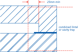
The single brick thick external leaf of a cavity wall can allow moisture into the cavity. Cavity trays should be used so that water drains outwards above openings.
Cavity trays over lintels should extend at least 25mm beyond the outer face of the cavity closer and cover the ends of the lintel. Where the lintel does not require a dpc, the lintel itself should have a suitable profile and durability and give complete protection to the top of the reveal and vertical dpc where provided.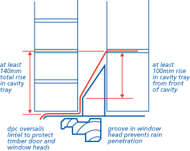
The upstand part of the cavity tray should be returned into the inner leaf masonry unless stiff enough to stand against the inner leaf without support.
In Scotland, all lintels should have a dpc built into the inner leaf.
In Scotland, Northern Ireland, the Isle of Man and areas of Very Severe exposure to driving rain, the upstand part of the damp-proof protection should be returned into the inner leaf of masonry.
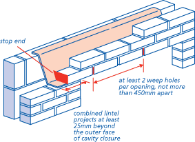
Where fairfaced masonry is supported by lintels:
- weep holes should be provided spaced at maximum 450mm intervals. Each opening should have at least two weep holes.
- cavity trays or combined lintels should have stop ends.
A cavity tray should be provided where the cavity is bridged by air bricks, etc. The dpc should extend 150mm beyond each side of the bridge.
Where not otherwise protected (eg by a roof at an appropriate level), a dpc tray should be provided over meter boxes.
A dpm should be provided behind meter boxes in areas of very severe exposure to driving rain.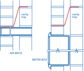
At the abutment of pitched roofs to cavity walls, stepped cavity trays should be provided as shown below. The lowest cavity tray should have two stop ends and a weep hole to allow water to drain from the cavity.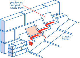
WALL TIES
Items to be taken into account include:
(a) type
The type of wall tie specified by the designer should be used.
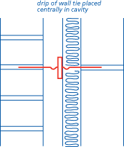
(b) position
If ties slope down to the inner leaf, if drips are off-centre or if ties have mortar droppings on them, water can cross the cavity.
The two leaves should be coursed so that the wall tie is level or slopes outwards.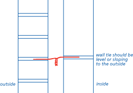
Ties should be bedded a minimum of 50mm into each leaf of the wall as work proceeds. The drip should face downwards. Ties should be built-in, not pushed into joints.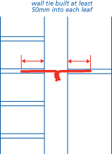
Where one leaf is built in advance of the other, the wall ties should project enough from the built leaf to bed at least 50mm into the unbuilt leaf.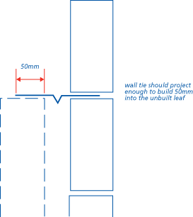
(c) spacing
Wall ties should be spaced above and below dpc as follows:
| Maximum spacing (mm) | ||
| Horizontally | Vertically | |
| General wall area | 900 | 450 |
| At jamb openings, movement joints, etc. | within 225 of opening |
not more than 300 |
At openings and movement joints, wall ties should be spaced at maximum 300mm centres vertically even if this means cutting cavity insulation to insert the tie.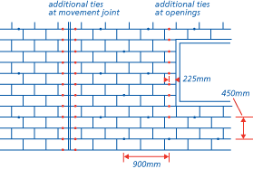
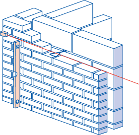
(d) use of partial fill insulation
Where partial cavity fill insulation is being used, it should be retained against the inner leaf by retaining devices. The retaining devices should be compatible with the wall ties and used in accordance with an assessment which complies with Technical Requirement R3.
Unless the independent assessment states otherwise, where partial cavity fill is being used the wall ties should be spaced more closely to provide adequate support and restraint for the 1200mm long boards. Ties should be spaced at 600mm centres horizontally and in vertical as well as horizontal rows, ie not staggered.
LINTELS
Items to be taken into account include:
(a) span and placing
Lintels should be the correct size for the opening and have the correct bearing at each end:
| Minimum bearing length (mm) | ||
| Span (m) | Simple lintel |
Lintel combined with cavity tray |
| Up to 1.2 | 100 | 150 |
| Over 1.2 | 150 | 150 |
Longer span lintels may require padstones (the design should be checked).
Setting out should ensure that lintels bear on a full block, where possible, or on a whole brick, and be installed level on a solid bed of a mortar. Soft or non-durable packing should not be used. Small pieces of cut brick or block should not be used around lintel bearings.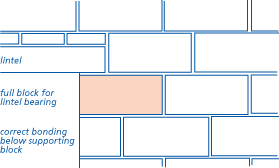
Lintels and masonry should form openings of the correct size for the frame of the window or door.
Concrete floor units or other heavy components which bear on lintels should be positioned carefully to avoid damage or shock load.
The lintel toe should:
- project past the window head
- have a flexible sealing compound between toe and window.
Brickwork or masonry should not overhang the lintel by more than 25mm.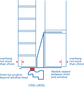
(b) thermal insulation
Insulation may help to prevent cold bridges at the heads of openings in external walls. The design should be checked for this requirement. Insulation should be provided to the underside of the lintel unless the manufacturer shows an alternative to prevent cold bridging.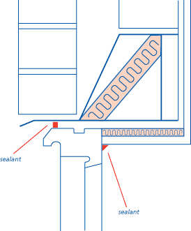
(c) use of dpc cavity trays
A separate cavity tray should be provided over some lintels if:
- the corrosion protection to the lintel is inadequate, and
- the shape of the lintel is unsuitable.
This should be checked with the designer or buyer.
In Scotland, Northern Ireland, the Isle of Man and areas of Severe or Very Severe exposure to driving rain, a cavity tray is required over all lintels. Reference should be made to Clause S4(e) for details of cavity trays.
All cavity trays should have stop ends where the outer leaf is fairfaced masonry.
(d) use of steel lintels
Where steel lintels are being used, the inner and outer leaf should be built up together to avoid twisting the lintel flange. The difference in height between the leaves should not exceed 225mm.
THERMAL INSULATION
A high standard of workmanship should be maintained to minimise the risk of damp penetration to the inside of the dwelling where cavity insulation is used.
In particular:
- mortar joints, including perpends, should be solidly filled with mortar
- mortar droppings should be removed from wall ties and the edges of insulation materials
- excess mortar should be struck smooth from the inside of the outer leaf.
Where insulation is built-in, manufacturers' instructions should be followed. These are normally printed on the insulation packaging and include a recommended sequence of construction.
Recessed joints should not be used where the cavity is to be filled with insulation.
In Northern Ireland and the Isle of Man it is not permissible to fill the cavity with pumped insulants, eg UF foam, at the time of construction.
In Scotland, it is not permissible to fill the full width of the cavity with any thermal insulants at the time of construction.
All retro-fill insulation materials (UF foam, blown mineral fibre and expanded polystyrene beads) should be installed by installers trained by the assessment holder and approved jointly by the assessment holder and the assessing organisation. The installer should be a member of a surveillance scheme acceptable to NHBC.
The first row of insulation boards or batts should be supported on wall ties, two ties to each board or batt.
Wall ties should coincide with horizontal joints in the insulation.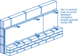
Where wall ties need to be closely spaced, for example at reveals, it is acceptable to make a clean cut neatly in the insulation to accept the extra ties. The insulation manufacturer's instructions should be followed.
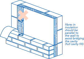
Insulation should be close butted with no gaps. Gaps provide routes for dampness, and condensation can form on the cold spots where insulation is missing.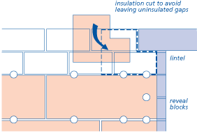
Insulation boards for partial fill should be stored flat without bearers otherwise they may distort making them difficult to fix against the wall. Warped boards should be rejected.
RENDERING
Items to be taken into account include:
(a) preparation of backing surface
The surface to be rendered should be free from dust, loose particles, efflorescence and organic growth.
Where necessary, surfaces should be treated to provide an adequate key by:
- raking out joints
- hacking the surface
- applying a bonding agent
- applying metal lathing
- applying a spatterdash coat, or
- other appropriate means.
The surface suction should be checked by splashing water onto the wall. The result should be observed and appropriate action taken as follows:
- if too much suction, spraying with water may be needed - do not use too much water
- if too little suction, a spatterdash coat or bonding agent may be needed
- if the background is too wet, delay rendering until conditions improve.
The design requirements should be checked where rendering is continuous over different materials. Corrosion-resistant metal lathing should be fixed across the joints or, alternatively, provision made to accommodate movement.
Expanded metal should be fixed with the correct side towards the wall (see manufacturers' literature). If metal lathing is used to bridge changes in background material, a separating strip, eg breather paper, should be fixed behind the lathing so that the render does not bond at the background joints. Lathing should be set away from the wall so that rendering can be forced through the mesh to achieve a good bond.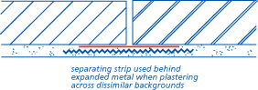
(b) mix
The mix proportions should be checked against the specification, especially whether sulfate-resisting cement should be used.
Mixes for rendering on brickwork using clay bricks with no limit on their soluble salt content (F2,S1 or F1,S1 to BS EN 771) should be as follows:
| Exposure conditions |
Undercoat mix proportions (by volume) |
Finishing coat mix proportions (by volume) |
| Parapets, freestanding walls, pillars, retaining walls and chimneys |
rendering not recommended |
|
| All walls other than those above | 1 : 5, sulfate-resisting Portland cement : sand, plus integral waterproofer | 1 : 5, ordinary Portland cement : sand, dry dashing strongly advised |
For backing brickwork, it should be ensured that sulfate-resisting cement which complies with Appendix 6.1-C is used in the mortar.
If water-resisting properties are required, Portland cement with a waterproofing agent already incorporated may be available. Otherwise, a waterproofing agent should be used and added to the rendering mix in strict accordance with manufacturers' instructions.
(c) application
The number and thickness of coats should be in accordance with the design.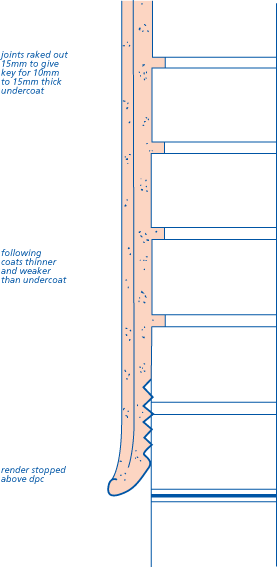
In Scotland, a spatterdash coat should be applied before the first render coat if the background is of Scottish common bricks and bricks to BS EN 771.
Undercoats should be applied at least 3 days before applying the following coat.
If coloured pigments are specified, batching should be undertaken with care to ensure colour consistency.
(d) cracking and crazing
Rendering should be free from significant cracking and crazing.
To avoid surface crazing:
- use properly graded sand (fine sand increases the risk of crazing)
- strong mixes should not be used as the finishing coat
- overworking, which causes laitance to be drawn to the surface, should be avoided
- the finishing coat should be kept damp for at least 3 days. In warm dry weather, spraying or protection by polyethylene sheet may be needed. Rendering should not be carried out during hot weather or in bright sunshine.
COLD WEATHER WORKING
Freshly laid mortar and render may fail if it freezes because the frozen water expands and forces apart the particles of mortar.
Admixtures which contain calcium chloride should not be used.
The use of air entraining agents in cold weather gives better frost resistance to set mortar but does not aid the set. The use of accelerating admixtures and other admixtures should not be relied on as an anti-freeze precaution.
Check what effect additives have on setting times. Cold weather slows setting, as do retarders. If the set is retarded too much, the next lift might squeeze out the mortar below.
Brick and blockwork should not be built nor rendering carried out when the air temperature is 2°C and falling.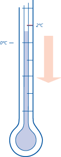
Walls should be protected from frost until the mortar has set sufficiently to resist frost damage. Covers should be provided to form a still air space to insulate the wall. Walling damaged by frost will not regain strength and should be taken down and re-built when conditions improve.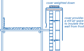
Reference should be made to Chapter 1.4 'Cold weather working' for more detailed advice.
HANDLING AND PROTECTION
Items to be taken into account include:
(a) avoidance of damage
It is cost effective to protect and store materials properly and maintain good quality control during construction.
(b) handling
The unloading of all bricks and blocks, especially facing bricks, preferably should be by mechanical means, directly onto a firm level surface. Bricks that are tipped on delivery or moved about the site in dumper trucks often have a high degree of wastage. Chipped or fractured bricks are not acceptable for facework.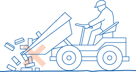

(c) storage
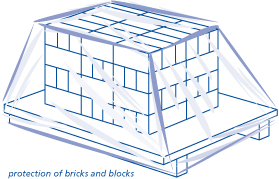
Stacks of bricks and blocks should be protected from rain, mud splashes, etc by covering with waterproof covers. Bricks and blocks that become excessively wet can suffer from:
- staining and efflorescence
- increased drying shrinkage with a greater risk of cracking
- lack of mortar adhesion to mud stained surfaces.
Cement should be stored off the ground and protected from weather. Sand should be prevented from spreading and be protected so that it remains clean.
The work place should be kept clean to reduce mortar splashes to a minimum. Any accidental mortar smears should be lightly brushed off the face after the mortar has taken its first set.
(d) workmanship
Materials should be handled with care during construction to avoid damage and staining. Badly chipped bricks should not be used for facework.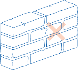
At night, the scaffold board closest to the brickwork should be removed to prevent rain splashing off boards onto facework. The inner board should be turned back onto other boards or placed on top of the day's work to protect cavities and voids from rain.
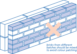
Unless bricks have been blended by the manufacturer, bricks from different batches should be mixed to avoid colour patching.
To reduce the risk of efflorescence, newly erected masonry should be covered. This also prevents the mortar being washed out of the joints by rain and stops masonry becoming saturated.

