


6.2 External timber framed walls
SITEWORK STANDARDS
| 6.2 - S1 | Sitework standards |
| 6.2 - S2 | Construction |
| 6.2 - S3 | Breather membranes |
| 6.2 - S4 | Wall ties |
| 6.2 - S5 | Insulation |
| 6.2 - S6 | Vapour control layers |
| 6.2 - S7 | Cladding |
| 6.2 - S8 | Control of fire |
| 6.2 - S9 | Services |
(a) meet the Technical Requirements
(b) take account of the design
(c) follow established good practice and workmanship
Sitework that complies with the design and guidance below will be acceptable for external walls of timber framed dwellings, substantially timber framed dwellings and wall panels.
All relevant information in a form suitable for the use of site operatives should be available on site before construction starts including:
- full set of drawings
- materials specification
- fixing schedules
- nailing details
- manufacturers' recommendations relating to proprietary items.
CONSTRUCTION
Items to be taken into account include:
(a) setting out
The substructure should be correctly set out to receive the timber frame which will be manufactured to close tolerances. The timber frame should be checked to ensure that it is erected accurately both on plan and vertically. The load from the frame should be supported as intended in the design.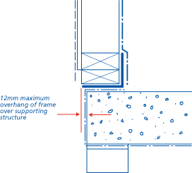
Ledges can form moisture traps. Where these occur protection should be provided.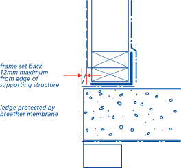
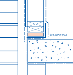
The bed between the frame and substructure should:
- not be more than 20mm thick
- be the full width of the frame
- support each stud
- be durable
- not deform under load.
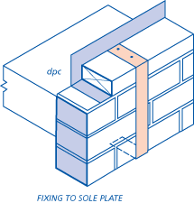
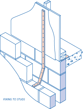
(b) anchoring the frame
The frame should be anchored to resist both lateral movement and uplift. Care should be taken to avoid splitting timber plates.
When shotfiring, care should be taken not to spall edges of masonry or slabs. When shotfiring into masonry, solid concrete blocks with a crushing strength of 7N/mm2 should be used, positioned to receive fixings.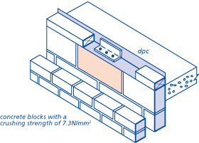
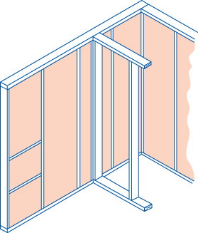
(c) fixing panels
All fixings should be as scheduled in the design including nailed joints and sheathing.
Wall panels should be securely fixed together and to floor and roof framing.
In Scotland, sole plates and head binder plates should be provided to bind the panels together where there are joints between wall panels. Joints in sole plates and head binder plates should not coincide with those of the panels.
In England, Wales, Northern Ireland and the Isle of Man, joists and roof trusses should bear directly over studs if head plates are not provided.
Individual studs should be not less than 37mm wide, at maximum 600mm centres, unless other adequate support is provided for wall boards and fixings and agreed by NHBC.
A lintel and cripple studs should be provided to any opening in loadbearing panels except when the opening does not affect the stud spacing or where the supported loads are redistributed by a perimeter joist.
Unless otherwise clearly specified by the designer, multiple studs should be included to support multiple joists.
Narrow, inaccessible gaps between studs which are difficult to insulate should be avoided.
(d) supporting claddings
Masonry cladding should not be supported on timber.
Wall ties should be flexible and fixed to studs.
Battens supporting lightweight cladding should be fixed to studs.
(e) fixing plasterboard
Plasterboard should be fixed in accordance with Chapter 8.2 'Wall and ceiling finishes' (Sitework).
Particular care should be taken at the junction between walls and roofs. Reference should be made to Chapter 8.2 'Wall and ceiling finishes' (Sitework).
(f) movement between timber frame wall and other elements
BALLOON CONSTRUCTION
In balloon construction, dwelling height studs are used to which the floor is attached. This form of construction is not commonly used in the United Kingdom. The timber frame designer's recommendations for differential movement allowances should be followed.
PLATFORM CONSTRUCTION
This is the use of storey height panels separated by floor joists.
When using this form of construction either the designer's recommendations should be followed or the following allowances used to accommodate differential movement:
| Location | Suspended timber ground floor when panels are supported on ground floor joists or perimeter joists | Other groundfloor construction |
| Ground floor openings | 5mm | 3mm |
| First floor openings | 12mm | 9mm |
| Second floor openings | 18mm | 15mm |
| Eaves and verges | Add 3mm to the allowance for openings on that floor | |
For timber framed buildings more than three storeys high allowances should be extrapolated from the table by 6mm for each additional storey.
The design should be checked to see how the differential movement is allowed for at openings.
At eaves and verges a gap should be left above the masonry which can close as the timber shrinks. Sealing the gap is not required if it is protected by the eaves overhang.
In buildings of four storeys or more it is important that the wall ties are capable of allowing for the likely differential movement.
Do not deviate from those specified.
The design should be checked to see if allowances are made for vertical or horizontal movement in the following locations:
- the eaves
- sills of openings
- heads of openings
- jambs of openings.
The design should specify the required allowance. If it does not the designer should provide details of the allowances.
An allowance for shrinkage should be made at the eaves.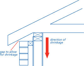
At sills of openings leave a gap sealed with a compressible sealant.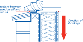
At heads of openings allow for a gap to open. Seal the gap with an expandable sealant or ensure it is well weathered. Do not fix lintels supporting outer leaf masonry rigidly to the timber frame. Allow space between the lintel and its clips for differential movement.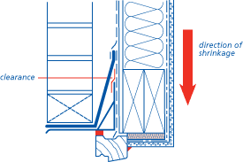
At jambs of openings allow for shear movement between masonry and joinery.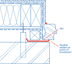
Where joinery (eg window frames) is fixed to the masonry, the design should be checked as special details may be required.
CLADDING FIXED TO THE FRAME
Allowances are not required around openings or at eaves and verges.
A gap, protected against rain penetration, should be left at horizontal junctions with masonry.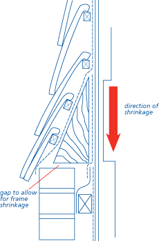
Shear movement should be allowed at vertical junctions with masonry.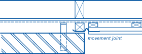
CHIMNEYS OR FLUES
A joint should be constructed between chimneys or flues which will prevent any load being transferred onto the chimney or flue.
(g) cavities
A cavity should be provided to reduce the risk of rain penetrating to the frame. The following minimum cavity widths, measured between the claddings and sheathings, should be provided:
| Cladding | Minimum cavity width |
| Masonry | 50mm nominal |
| Render on unbacked lathing | 50mm nominal |
| Render on backed lathing | 25mm nominal |
| Vertical tile hanging without underlay | No vertical cavity required when a breather membrane is fitted to the sheathing |
| Other cladding | 10mm |
The cavity should be extended at least 150mm below dpc, to form drainage to the cavity, and should be kept clear. Weep holes should be provided where necessary to prevent water build up in the cavity.
Deviations in vertical alignment should not exceed 10mm in any storey height.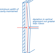
BREATHER MEMBRANES
Special attention should be given to the following details:
- laps, which should be at least 100mm on horizontal joints and 150mm on vertical joints as shown in the following diagram
- direction of laps, upper layers should be fixed over lower layers to ensure rain runs away from the sheathing. Vertical joints should be staggered wherever possible
- fixing should be at regular intervals to prevent damage by wind and should be not less than 500mm centres and in accordance with manufacturers' instructions
- marking the stud positions for wall tie fixing
- shedding water away from the lowest timber
- use of self extinguishing grade membrane
- use of high performance breather membrane in areas of Very Severe exposure (unless the alternatives given in Design Clause D4(c) are adopted)
- use of fixings described in Chapter 6.2 (Materials).
Damaged membranes should be repaired or replaced.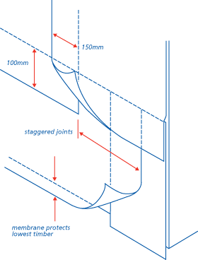
When bitumen impregnated fibre building board is used and a breather membrane is not specified the joints of the boards should be closely butted.
When a breather membrane is not required the bottom frame members should be protected from water running down the cavity.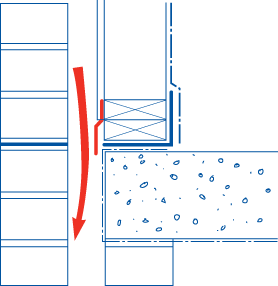
WALL TIES
Wall ties should:
- be fixed to studs not sheathing
- slope away from the sheathing towards the cladding
- be sufficiently flexible to take up differential movement
- be kept clean and free from mortar droppings.
Wall ties should be spaced as required by the design but not greater than 600mm horizontal and 450mm vertical maximum spacing. At jambs of openings spacing should be a maximum of 300mm vertically with ties set within 300mm of the masonry reveal. In certain locations the design may require closer spacings.
INSULATION
Insulation should cover the whole wall area between studs. No gaps should be left:
- against studs or rails
- at corners
- against noggings
- at junctions with partitions.
Insulation with a backing membrane of any material shall be installed with the backing on the warm side of the insulation.
VAPOUR CONTROL LAYERS
Before fixing a vapour control layer the framing timbers should have a moisture content of 20% or less.
The vapour control layer should be fixed on the warm side of the insulation and frame.
The vapour control layer should be formed of the material specified by the design. Minimum 500 gauge polyethylene sheet or vapour control plasterboard should be used. Where vapour control plasterboard is used joints between sheets should be positioned on studs or noggings and the joints should be filled, taped and finished.
Where polyethylene is used all joints in the vapour control layer should have at least 100mm laps and be located on studs or noggings.
Vapour control layers should be fixed at 250mm centres to the top and bottom of the frame, at laps and around openings.
When cutting vapour control plasterboard care should be taken not to displace the vapour control material.
Any holes made in a vapour control layer should be made good and sealed.
The vapour control layer should cover the entire external framed wall area including rails, studs, reveals, lintels and sills.
The vapour control layer should lap with the dpc.
CLADDING
Allowance for differential movement between various components should be made as detailed in Clause S2 of this Chapter.
No horizontal batten supporting cladding should be in contact with the sheathing except in the case of tile hanging.
The cavity should be ventilated although it is not necessary to provide through ventilation. Where wall areas are divided by cavity barriers (see Design clause 6.2 - D7) the ventilation openings should be adjacent to barriers at the lower level.
The ventilation openings should be equivalent to open brick perpends every 1.5m.
Ventilation slots should be placed to prevent the ingress of rain or should be below the lowest timber. Weather protected proprietary perpend ventilators are available.
The cavity should be kept clean, free of obstructions and should be capable of draining freely.
All proprietary cladding should be fixed in accordance with manufacturers' instructions.
Masonry cladding should be constructed in accordance with Chapter 6.1 'External masonry walls'.
CONTROL OF FIRE
CAVITY BARRIERS
Cavity barriers should be installed in positions detailed by the design and relevant Building Regulations.
Cavity barriers should be formed of materials specified in the design. If no specification is available the advice of the designer should be obtained.
Horizontal cavity barriers (except under eaves) should be protected with a dpc tray. The tray should have a minimum upstand of 100mm. Alternatively polyethylene encased cavity barriers providing a minimum upstand of 100mm should be used.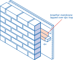
Vertical timber cavity barriers should be protected from moisture by a dpc.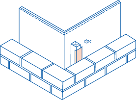
FIRE-STOPPING
Fire-stops should be installed in positions detailed in the design and relevant Building Regulations.
Only those materials specified in the design should be used for fire-stopping.
If details of fire-stop design, location and materials are not available they should be verified with the designer before construction commences.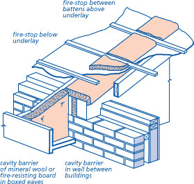
SERVICES
Services should not pass through separating wall cavities.
Service outlets should not impair the fire resistance of floors and walls.
In Scotland services are not permitted within a timber framed separating wall cavity.
Notching or holing structural timber members should be carried out as detailed in the design. If these details are not available the designer should be consulted before such operations are started.

