6.10 Light steel framed walls and floors
SITEWORK STANDARDS
(a) meet the Technical Requirements
(b) take account of the design
(c) follow established good practice and workmanship
Sitework that complies with the design and the guidance below will be acceptable for external and internal walls, and floors using light steel framing.
Information in a form suitable for the use of site operatives should be available on site before and during construction including:
- relevant drawings
- materials specification
- fixing schedules
- fixing details
- manufacturers' recommendations relating to proprietary items.
CONSTRUCTION OF LOADBEARING WALLS AND EXTERNAL INFILL WALLS
Items to be taken into account include:
(a) setting out
The structure onto which the light steel frame is to be erected should be correctly set out in accordance with the design. The loads from the light steel frame should be supported as detailed in the design.
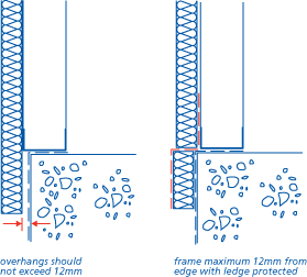
The supporting structure may have local deviations in level along its length and some packing will be required to achieve the required tolerances and to provide for effective load transfer.
The following guidance should be used, unless the frame manufacturer confirms otherwise:
| Gap under base rail | Acceptable packing |
| less than 10mm | provide shims under each stud position |
| 10 - 20mm | provide shims under each stud position and grout under the whole length of the base rail with cement:sand mortar |
| more than 20mm | obtain advice from the frame designer/manufacturer - remedial work to the substructure may be required before erection commences |
Shims should be of pre-galvanised steel. Plastic or timber shims are not acceptable.
(b) accuracy of walls
Wall frames should be checked to ensure that they are dimensionally accurate before erection commences.
All light steel framing should be correctly positioned, square and plumb. The verticality of a light steel frame, relative to its base should be +/- 5mm per storey.
The horizontal position of the base rail should not vary in alignment by more than 5mm in 10m.
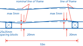
(c) anchoring the frame
The frame should be anchored to resist both lateral movement and uplift as required by the design.
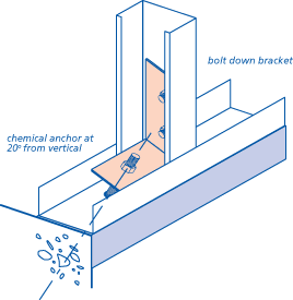
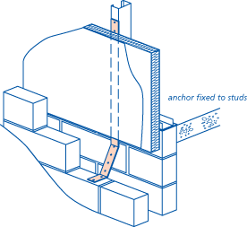
Shot-fired fixings should observe a minimum edge dimension to prevent spalling at edges of masonry or slabs. When shotfiring into masonry, solid concrete blocks with a minimum crushing strength of 7.3 N/mm2 should be used, positioned to receive fixings.
Where the design incorporates gas membranes (methane or radon) fixings should not puncture them but where this is unavoidable the penetration should be sealed.
(d) alterations
Steelwork should only be altered with the approval of the designer. Welded or flame cut edges should be cleaned before being treated with a zinc-rich paint to prevent corrosion.
(e) fixing panels
Wall panels should be securely fixed together and to floors in accordance with the design.
(f) masonry claddings
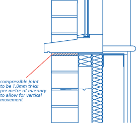
Soft joints should be provided to allow for differential movement. A gap of 1mm per metre of wall height should be provided at openings and soffits.
(g) supporting claddings
Masonry claddings should not be supported by the light steel framed walls unless shown in the design.
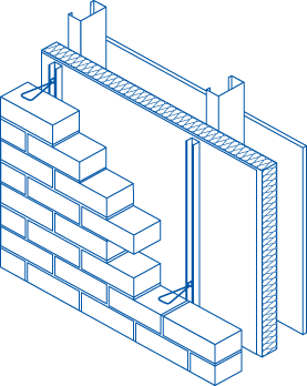
Masonry claddings may be tied to the light steel framed walls with flexible wall ties fixed through to the studs.
Lightweight claddings should be supported by the light steel framed walls on battens or by other suitable means unless shown otherwise in the design.
(h) fixing wallboard
Plasterboard should be fixed in accordance with Chapter 8.2 'Wall and ceiling finishes' (Sitework).
Other wallboards should be fixed in accordance with the manufacturer's recommendations.
Wallboards should be attached to light steel studs using self-drilling, self-tapping screws at not more than 300mm centres.
Other fixings should be in accordance with the manufacturer's recommendations.
Particular care should be taken at the junction between walls and roofs. Reference should be made to Chapter 8.2 'Wall and ceiling finishes' (Sitework).
(i) movement between steel frame wall and other elements
Movement joints between light steel framed walls and other elements should be provided in accordance with the design.
A joint should be constructed between the frame and any chimney or flue to prevent load transfer onto the chimney or flue.
(j) cavities
A clear cavity should be provided to reduce the risk of rain penetrating to the frame. The following minimum cavity widths, measured between the claddings and sheathings, should be provided.
| Cladding | Cavity width |
| Masonry | 50mm nominal |
| Render on backed lathing | 25mm nominal |
| Vertical tile hanging without underlay | No vertical cavity required when a breather membrane is provided |
| Other cladding* | 15mm nominal |
* see Chapter 6.9 'Curtain walling and cladding'
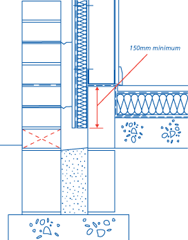
The cavity should be extended at least 150mm below the dpc and be kept clear to allow drainage. Weep holes or other suitable means of drainage should be provided where necessary to prevent water build up in the cavity.
INSULATION
Insulation should cover the whole external face of the wall and extend 150mm below the bottom rail to maintain a warm frame.
Insulation boards should be tightly butted. Joints between boards should be taped with a suitable tape where required by the design.
Foil-faced insulation boards with an integral facing on one side only should be fixed with the foil face on the cavity side.
BREATHER MEMBRANES
Breather membranes should be lapped so that each joint is protected and moisture drains outwards.
Laps should be at least 100mm on horizontal joints and 150mm on vertical joints.
WALL TIES AND FIXINGS
Wall ties should:
- be fixed through to the studs
- be inclined away from the light steel framing
- be kept clean and free from mortar droppings.
Wall ties should be spaced as required by the design but not less than 3.7 ties/m2 e.g. spaced at a maximum of 600mm horizontally and 450mm vertically. At jambs of openings the spacing should be a maximum of 300mm vertically with ties set within 225mm of the masonry reveal.
Other fixings should be of the type specified, and be fixed in accordance with the design.
VAPOUR CONTROL LAYERS
Where required by the design a vapour control layer should be fixed on the warm side of the insulation and frame.
The vapour control layer should be of the material specified in the design. Minimum 500 gauge polyethylene sheet or vapour control plasterboard should be used.
Where polyethylene sheet is used all joints in the vapour control layer should have at least 100mm laps, located on studs or noggings. Double sided tape or adhesive should be used as a temporary fixing before the wall board is fixed.
Where vapour control plasterboard is used, joints between sheets should be positioned on studs or noggings. When cutting vapour control plasterboard, care should be taken not to displace the vapour control material.
Any holes made in the vapour control layer should be made good and sealed.
The vapour control layer should cover the external wall including base rails, head rails, studs, lintels and window reveals.
At the base of the wall the vapour control layer should overlap the base rail.
CLADDING
Masonry cladding should be constructed in accordance with Chapter 6.1 'External masonry walls' (Design and Sitework).
For other claddings reference should be made to Chapter 6.9 'Curtain walling and cladding' (Design and Sitework).
A clear cavity should be provided between the sheathing and the cladding. The cavity should be drained. Where wall areas are divided by cavity barriers, the drainage of the cavity should be maintained or cavity trays and weep holes installed.
Drainage at the base of the cladding system should be equivalent to 500mm2/m run (e.g. for masonry, one open perpend every 1.5m).
Openings for drainage should be placed to prevent the ingress of rain.
The cavity should be kept clean, free of obstructions and should be capable of draining freely.
CONSTRUCTION OF NON-LOADBEARING INTERNAL WALLS
Items to be taken into account include:
(a) setting out and workmanship
Partitioning should be correctly positioned, square and plumb.
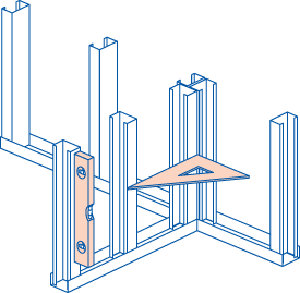
Studs should be spaced at maximum 450mm or 600mm centres to suit the wall board thickness as required by the design. Extra studs should be provided at openings, if required by the design.
(b) size of steel members
Non-loadbearing partitions should be constructed in accordance with the design.
(c) alterations
Steelwork should only be altered with the approval of the designer. Welded or flame cut edges should be cleaned and treated with a zinc-rich paint to prevent corrosion.
(d) support and fixings
Non-loadbearing partitions should be fixed in accordance with the design. They should be fixed to the floor on which they stand, at the head, to each other and to abutting walls. Noggings or extra studs should be used where shown in the design.
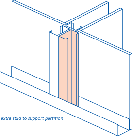
Non-loadbearing partitions should not be wedged against floor joists, ceiling joists or roof trusses. Allowance should be made for the floor joists, ceiling joists or roof trusses to deflect so that the partition does not become loadbearing.
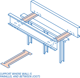
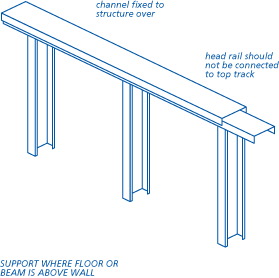
Noggings or straps should be provided as required to support fittings, such as radiators, wall-mounted boilers, sanitary fittings, kitchen units, etc.
Fixing and finishing of partitions should be in accordance with Chapter 8.2 'Wall and ceiling finishes' (Sitework).
SEPARATING WALLS
The design details should be carefully followed.
There should be no gaps in the:
- mineral wool quilt or batts
- wallboard layers
- fire-stopping.
Services in or adjacent to separating walls should be installed in accordance with the design. (See clause 6.10 - S17).
LIGHT STEEL JOISTS
Items to be taken into account include:
Where required by the design ground floor joists should be protected by the application of a two-coat bitumen based coating, or have a two-coat liquid asphaltic composition applied. Ring beams to ground floors should be totally protected and joists protected for 300mm adjacent to the support or ring beam.
Joist spacings should be as shown in the design.
Joist support cleats should be of the correct type and fitted in the specified location with the fixings specified in the design.
Where joists are fitted directly to light steel wall studs, pre-drilled holes should be correctly aligned before making the final connection.
Fixing holes should not be enlarged and additional holes should not be cut without the consent of the designer.
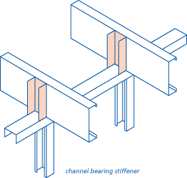
Where required, web stiffeners should be properly fitted to ensure good bearing.
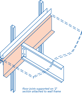
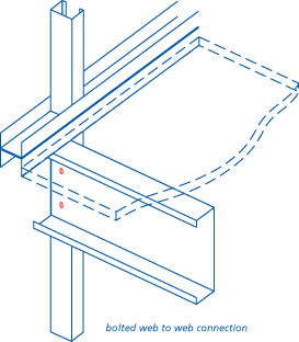
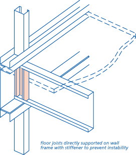
Joists should be accurately cut to length in the factory to ensure a tight fit. The correct type, size and number of fixings should be as specified at every connection.
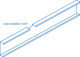
Some end notching of light steel joists may be required for interconnection of trimming joists. This should be in accordance with the design. Notches elsewhere in the span are unacceptable. Welded or flame cut edges should be cleaned and treated with zinc-rich paint to prevent corrosion.
Where light steel joists are supported by steel joists, cleats or web stiffeners should be used in accordance with the design.
Joists may be doubled up to support partitions or to form trimmers. Fixings should be in accordance with the design and should be properly installed. Bolted connections should be tightened to the torque given in the design.
Bridging and blocking should be provided in accordance with the design to prevent roll.
Floors constructed with joists with an asymmetric web (e.g. of 'C' or Sigma profile) can cause the floor to 'roll'.
To avoid this one of the following alternatives should be provided where the span exceeds 3.5m for 'C' joists or 4.2m for Sigma joists unless otherwise specified in the design:
- a continuous line (or lines) of proprietary steel herringbone strutting provided between the joists. The pairs of ties should have a physical gap between them so that they do not rub against each other at the cross-over point and cause noise

- solid blocking provided to every third pair of joist with ties between

- joists alternately reversed and tied together in pairs

- joists alternately reversed and continuous ties (e.g. resilient bar) fixed to the joist flanges.

Where joists bear onto steelwork or are supported by cleats, blocking is not necessary adjacent to the supports.
Joists should only be altered with the approval of the designer. Welded or flame cut edges should be cleaned and treated with a zinc-rich paint to prevent corrosion.
The flanges of a light steel joist should not be notched unless in accordance with the design.
Drilling or punching through the web should only be carried out within recognised limits.
Unstiffened holes through the web should be carried out within the following limits:
- a rectangular hole or slot should not exceed 40% of the overall depth of the member. The length of the hole should not exceed three times the depth of the hole
- the diameter of circular holes should not exceed 60% of the depth of the member
- unstiffened holes should be at least the depth of the member apart and at least 1.5 times the depth from the end of the member.
Where external walls, not constructed from light steel framing, are to be stabilised by a connection to the floor, straps may be required. Straps will generally be fixed to the web of the joist, to suit the masonry courses.
Where joists run parallel to the wall, straps should be supported on noggings fixed between the joists. Straps should be placed at a maximum of 2m apart and carried over three joists. Packing should be provided between the wall and the first joist.
Straps should be fixed with suitable bolts, screws or rivets and should bear on the centre of bricks or blocks, not across mortar joints.
Where joists overlap on loadbearing intermediate walls they should be fixed together with bolts or screws to prevent the floor decking being pushed up or the ceiling being cracked when the cantilevered part of the joist moves upwards.
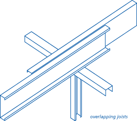
Where joists are continuous over loadbearing intermediate walls, they should be reinforced as required by the design.
Items to be taken into account include:
(a) decking
Flooring should be attached using self-drilling, self-tapping screws, ring shank nails or other approved fixings in accordance with the design at centres not more than 300mm. T&g joints should be glued.
(b) ceilings
Plasterboard should be fixed in accordance with Chapter 8.2 'Wall and ceiling finishes' (Sitework) using self-drilling, self-tapping screws.
Other ceiling boards should be fixed in accordance with the manufacturer's recommendations.
SEPARATING FLOORS
The floating part of a floor should be completely separated from the main structure and surrounding walls by a resilient layer.
All joints should be glued where boards are laid loose over insulation without battens.
SERVICES
Services and service outlets should be installed in accordance with the design.
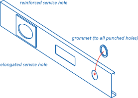
Light steel studs should not be notched to accommodate services. Holing of structural light steel members should only be carried out as detailed in the Clause 6.10 - S11 unless approved by the designer. Welded or flame cut edges should be cleaned and treated with zinc-rich paint to prevent corrosion.
Cutting of service holes on site should be avoided since badly cut edges can have an adverse affect on the durability of the frame and may cause damage to pipes and cables.
Grommets should be used around the edge of service holes to protect electrical cables and reduce the risk of bimetallic corrosion between the light steel framing and copper pipes.
Swaged holes will not require grommets for the passage of electric cables and plastic piping.
In Scotland services are not permitted within a separating wall cavity.
CONTROL OF FIRE
Items to be taken into account include:
(a) walls
Walls should be constructed in accordance with the design and relevant Building Regulations to achieve the necessary fire resistance.
(b) floors
Floors should be constructed in accordance with the design and relevant Building Regulations to achieve the necessary fire resistance.
(c) cavity barriers and fire-stops
Cavity barriers and fire-stops should be installed in positions detailed by the design and relevant Building Regulations.
Service penetrations in floors between dwellings should be fire-stopped. There should be no holes or gaps for smoke to penetrate once the fire-stopping has been installed.


