


5.3 Drainage below ground
SITEWORK STANDARDS
(a) meet the Technical Requirements
(b) take account of the design
(c) follow established good practice and workmanship
Sitework that complies with the design and the guidance below will be acceptable for drainage below ground.
PRELIMINARY WORK
Check that the following are as specified in the design:
- invert levels and locations of existing sewers
- ground floor levels of dwellings
- external finished levels.
Percolation tests should be verified where treated effluent disposal is through field drains.
The length of any field drains specified in the design should be accommodated within the site boundaries.
EXCAVATION
Items to be taken into account include:
Drain runs and depths should be set out from benchmarks previously checked and verified. Any discrepancies in dimensions, and any ground conditions requiring modification to the design, should be reported immediately. Any resulting variations should be recorded and distributed to all concerned.
Excavate to the depths shown on the drawings. If any trench is excavated lower than the designed bottom level, it should be re-filled to the designed level to allow for the bedding to be continuous. Fill material should be:
- granular material, or
- concrete mix GEN 1 or ST 1/2 (not for field drains).
Hard spots should be undercut and removed, so that local stress points under pipes are avoided.
Soft spots should be filled with suitable well-compacted material.
Trenches should be as narrow as possible within working limits, allowing at least 150mm working space on each side of the pipe.
Foundation bottoms should be lower than adjacent drainage trenches.
Where the bottom of a trench is below foundation level, the trench should be filled with concrete to a suitable level.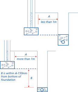
LAYING PIPEWORK
Items to be taken into account include:
Pipes should be firmly supported throughout their length and bedded as specified in the design.
Bricks, blocks or other hard material should not be used as temporary supports to achieve the correct gradients, as they may create hard spots which can distort the completed pipe run.
Pipes should be either:
- bedded on granular material, minimum 100mm deep or
- laid directly on the trench bottom, where the trench bottom can be accurately hand trimmed with a shovel but is not so soft that it puddles when walked on.
Depressions should be formed where necessary in the trench bottom to accommodate pipe joints.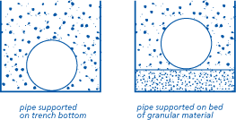
| Nominal pipe size [mm] | Granular material for bedding | |
| rigid pipes | flexible pipes | Material (complying with BS EN 13242) |
| 100 | 110 | 4/10mm pipe bedding gravel |
| 150 | 160 | 2/14mm pipe bedding gravel or 4/10mm pipe bedding gravel |
Proprietary pipes should be supported in accordance with manufacturers' recommendations. Some proprietary systems permit a minimum of 50mm depth of bedding in certain circumstances.
Generally, for 150mm diameter and 100mm diameter drains, a bed and surround of 10mm pea gravel (to a thickness of 100mm all round the drain) will be acceptable for drains under gardens, paths and drives.
Pipes should have flexible joints, installed in accordance with manufacturers' recommendations.
Sidefill and backfill should be placed as soon as the pipes have been bedded, jointed and inspected.
For proprietary systems, sidefilling and backfilling should be carried out in accordance with manufacturers' recommendations. Sidefill should be either:
- granular material (see table to Clause S4(a)), or
- selected backfill material from the trench excavation, ie free from:
- stones larger than 40mm
- clay lumps larger than 100mm
- timber
- frozen material
- vegetable matter.
GENERAL BACKFILL
Normally the excavated material from the trench will be suitable for backfilling above the selected material. General backfill material should be free from:
- boulders
- building rubble
- timber
- vegetable matter.
PLACING BACKFILL
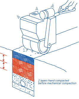
Backfill should be placed in layers not deeper than 300mm, and should be well compacted. Mechanical compacting should only be used when compacted backfill is at least 450mm above the crown of the pipe.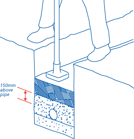
PROTECTION OF PIPEWORK
Items to be taken into account include:
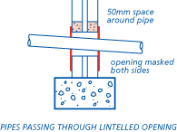
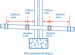
Pipes passing through substructure walls should accommodate movement. This may be achieved by:
- a 50mm clearance all round, or
- a sleeve, with 50mm clearance all round and suitably sealed
- if built in, connecting on both sides of the wall to pipes with flexible joints located not more than 150mm from the face of the wall. Flexible joints should be made in accordance with the pipe manufacturer's recommendations.
Where drains pass under roads and drives, the final compaction should be sufficient to prevent later settlement.
RIGID PIPES
Rigid pipes less than 1.2m below the road surface should, where necessary, be protected from damage by concrete encasement not less than 100mm thick, and having movement joints formed with compressible board at each socket or sleeve joint face.
Flexible joints should remain flexible.
FLEXIBLE PIPES
Flexible pipes less than 0.9m below the road surface should be protected by concrete bridging slabs or should be surrounded with concrete reinforced as appropriate.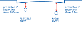
GARDEN AREAS
Where flexible pipes are not under a road and have less than 0.6m cover they should, where necessary, have concrete paving slabs laid as bridging above the pipes, with at least 75mm of granular material between the top of the pipe and underside of the slabs.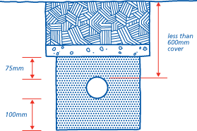
Where rigid pipes have to be encased in concrete, movement joints of 13mm thick compressible board should be provided around the spigot next to the socket, either at each joint or at not more than 5m intervals.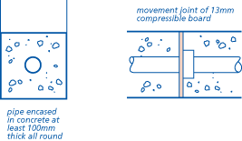
ACCESS POINTS AND GULLIES
Items to be taken into account include:
All access points should be located where shown on the drawings. They should:
- be accessible for rodding and cleaning
- not cross boundaries or kerb lines.
Ensure that inspection chambers and manholes are of sufficient size for the depth of invert. Do not exceed the invert depth for the particular fitting or chamber. Reference should be made to Appendix 5.3-A.
Manholes should be constructed or installed at the correct level, so that the covers will align with the adjacent ground. Gullies should be adequately bedded, set level and square and kerbed, where necessary.
The minimum specification for traditional manholes and inspection chambers is as follows:
BASE
Concrete not less than 100mm thick.
WALLS
Brick, blockwork or concrete should be appropriate for ground conditions. Generally 100mm minimum thickness is suitable for depths up to 0.9m where no vehicular traffic loads are encountered and there is no ground water pressure. Elsewhere, 200mm minimum thickness should be provided.
RENDERING
Rendering, if required, should be applied to the external faces of the wall.
BENCHING
Benching should be steel trowelled to provide:
- a smooth finish
- rounded corners
- a fall of not less than 1:12
- a good foothold.

Proprietary systems should be installed strictly in accordance with manufacturers' instructions. Adaptors, couplers and sealing rings should be installed correctly and only the lubricants and solvents specified by the manufacturer used.
Proprietary manholes should not be used at a depth greater than that for which they have been assessed as suitable.
Manhole covers and gully grids should be of the correct type for the proposed location. Proprietary items (eg covers to plastic manholes) should be in accordance with manufacturers' recommendations.
INSPECTION/MANHOLE COVERS AND FRAMES
- Group 1 - Areas which can only be used by pedestrians and pedal cyclists
- Group 2 - Footways, pedestrian areas and comparable areas, car parks or car parking decks
- Group 3 - For gully tops installed in the area of kerbside channels of roads which when measured from the kerb edge, extend a maximum of 0.5m into the carriageway and a maximum of 0.2m into the footway
- Group 4 - Carriageways of roads (including pedestrian streets), hard shoulders and parking areas, for all types of road vehicles.
Covers used for manholes within buildings should be airtight and mechanically secured.
Covers used for septic tanks, cesspits and settlement tanks should be lockable.
CESSPOOLS
Items to be taken into account include:
Cesspools should be impermeable to their contents and to subsoil water. They may be constructed of brickwork, concrete, glass reinforced concrete, glass reinforced plastics or steel.
Brickwork should be of engineering bricks, laid in cement mortar and at least 220mm nominal thickness.
In-situ concrete should be at least 150mm thick.
Cesspools should be covered and ventilated.
Cesspools should be sited at least 7m from a dwelling, but within 30m of a vehicle access to facilitate emptying.
Cesspools should be provided with access for emptying or de-sludging and cleaning. All such access points should have no dimension less than 600mm and be provided with lockable covers.
The inlet of a cesspool should be provided with access for inspection.
Cesspools should have no openings except the inlet, the vent and the inspection access.
SEPTIC TANKS
Items to be taken into account include:
Satisfactory outfall disposal is essential where septic tank sewage disposal is installed. Environment Agency consent may be needed in England and Wales. In Northern Ireland the Environment and Heritage Service should approve proposals, in Scotland the Scottish Environment Protection Agency should approve proposals. Check that this approval has been obtained before starting drainage work.
Ground conditions may preclude the use of septic tanks in some locations. NHBC will require evidence of a satisfactory percolation test where a septic tank drainage system is to be installed. See Appendix 5.3-B.
Septic tanks should be sited taking account of topography to ensure that water is drained away from the building.
Septic tanks should be impermeable to their contents and to sub-soil water. They may be constructed of brickwork, concrete, glass reinforced concrete, glass reinforced plastics or steel.
Brickwork should be of engineering bricks, laid in cement mortar and at least 220mm thick.
In-situ concrete should be at least 150mm thick.
Septic tanks should be covered and ventilated.
Septic tanks should be sited at least 7m from a dwelling, but within 30m of a vehicle access to facilitate emptying. In Scotland, they should be at least 5m from a dwelling and a boundary. Septic tanks should be provided with access for emptying or de-sludging and cleaning. All such access points where entry is required should have no dimension less than 600mm and be provided with lockable covers.
The inlet and outlet of a septic tank should be provided with access for inspection.
Provision should be made to limit the velocity of the flow to a septic tank. For drains up to 150mm diameter, the velocity may be limited by laying the last 12m of the incoming drain at a gradient not steeper than 1:50. A dip pipe should be provided, with the top limb rising above scum level and the bottom limb extending about 450mm below top water level.
SURFACE WATER SOAKAWAYS
Items to be taken into account include:
Where possible soakaways should be built on land lower than, or sloping away from, buildings. Soakaways should generally be sited at least 5m from the foundations of a building.
NHBC may require a percolation test for a soakaway. If the ground is free draining and granular, a test may not be necessary. However, if there is any doubt about the ground, or if there is a large quantity of run-off into the soakaway which may swamp the ground, a percolation test may be required.
Information on percolation tests is given in Appendix 5.3-E.
Small soakaways are holes filled with granular material, eg broken brick, crushed rock or gravel, with particle size 10mm to 150mm. PVC sheet or concrete blinding should be laid over the fill to prevent topsoil being washed down into the soakaway.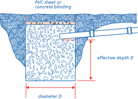
For large soakaways, a pit is lined with dry jointed or honeycomb brickwork.
Alternatively, perforated precast concrete rings or segments may be laid dry and surrounded with granular material.
The volume of large soakaways should be calculated to ensure they are of suitable capacity. Refer to Appendix 5.3-E or BRE Digest 365.
TESTING
Inspection and testing should be arranged when required by the Local Authority, the sewerage undertaker and NHBC.
Before backfilling, visual inspections are required and the Builder is advised to test.
When the dwelling is handed over, the system must be in full working order and free from obstruction.
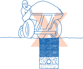
PROTECTION OF WORK
Damaged drainage will not be accepted. It is recommended that no heavy loading or underground work is permitted above or near unprotected drainage, and that dumpers, trucks, fork lifts or other heavy vehicles are not driven along or near pipe runs.