5.3 Drainage below ground
Appendix 5.3-A
| Minimum dimensions for access fittings and chambers | ||||||
|---|---|---|---|---|---|---|
| Type | Depth to invert from cover level (m) |
Internal sizes | Cover sizes | |||
| Length x Width (mm x mm) |
Circular (mm) |
Length x Width (mm x mm) |
Circular (mm) |
|||
| Rodding eye |
As drain but min 100 | Same size as pipework1 |
||||
| Access fitting | ||||||
| small | 150 diam 150 x 100 |
0.6 or less, except where situated in a chamber |
150 x 100 | 150 | 150 x 1001 | Same size as access fitting |
| large | 225 x 100 | 225 x 100 | 225 | 225 x 1001 | ||
| Inspection chamber | ||||||
| shallow | 0.6 or less 1.2 or less |
225 x 100 450 x 450 |
190 2 450 |
- Min 430 x 430 |
190 1 430 |
|
| deep | greater than 1.2 | 450 x 450 | 450 | max 300 x 300 3 | Access restricted to max 3503 |
|
Notes
1 The clear opening may be reduced by 20mm in order to provide proper support for the cover and frame.
2 Drains up to 150mm.
3 A larger clear opening cover may be used in conjunction with a restricted access. The size is restricted for health and safety reasons to deter entry.
| Minimum dimensions for manholes | |||||
|---|---|---|---|---|---|
| Type | Size of largest pipe (DN) (mm) | Min internal dimensions1 | Min clear opening size1 | ||
| Rectangular length and width (mm) | Circular diameter (mm) | Rectangular length and width (mm) | Circular diameter(mm) | ||
| Manhole | |||||
| less than 1.5m deep to soffit | equal to or less than 150 225 300 greater than 300 | 750 x 675 7 1200 x 675 1200 x 750 1800 x (DN+450) | 10007 1200 1200 The larger of 1800 or (DN+450) | 750 x 675 2 1200 x 675 2 | na 3 |
| greater than 1.5m deep to soffit | equal to or less than 225 300 375 - 450 greater than 450 | 1200 x 1000 1200 x 1075 1350 x 1225 1800 x (DN+775) | 1200 1200 1200 The larger of 1800 or (DN+775) | 600 x 600 | 600 |
| Manhole shaft 4 | |||||
| greater than 3.0m deep to soffit pipe | Steps 5 | 1050 x 800 | 1050 | 600 x 600 | 600 |
| Laddder 5 | 1200 x 800 | 1200 | |||
| Winch 6 | 900 x 800 | 900 | 600 x 600 | 600 | |
Notes
1 Larger sizes may be required for manholes on bends or where there are junctions.
2 May be reduced to 600 by 600 where required by highway loading considerations, subject to a safe system of work being specified.
3 Not applicable due to working space needed.
4 Minimum height of chamber in shafted manhole 2m from benching to underside of reducing slab.
5 Min clear space between ladder or steps and the opposite face of the shaft should be approximately 900mm.
6 Winch only - no steps or ladders, permanent or removable.
7The minimum size of any manhole serving a sewer (i.e any drain serving more than one property) should be 1200mm x 675 mm rectangular or 1200mm diameter.
Reproduced from Tables 11 and 12 of Approved Document H to the Building Regulations by permission of HMSO.
Appendix 5.3-B
Percolation test procedure for septic tank installations
- Excavate a hole 300mm square x 250mm deep below the proposed invert level of the land drain.
- Fill the hole with water to a depth of 250mm and allow to drain away over night.
- Refill to a depth of at least 250mm and note the time taken (in seconds) to drain away completely.
- Repeat the exercise two more times and calculate the average of the three results, as follows:
percolation value (s) = 
Results
| percolation value | suitability |
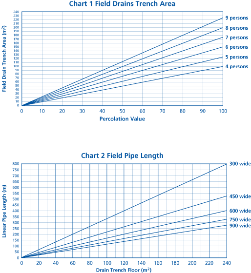
| up to 100 | use Appendix 5.3-C Chart 1 to determine field drain area |
| 100 to 140 | use Appendix 5.3-C Chart 1 but with underdrains* |
| over 140 | field drains unsuitable |
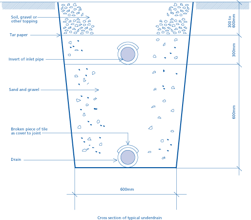
* Where underdrains are necessary, drainage trenches should be constructed not less than 600mm deeper than the pipe level specified in the design, and the lower part filled with pea gravel (see Appendix 5.3-D)
A second system of drainage pipes should be laid on the bottom of the trenches to convey surplus drainage to an outfall in a surface ditch or watercourse.
Underdrains are costly, and a secondary treatment system able to produce an effluent suitable for surface discharge may be preferable.
Appendix 5.3-C
Septic tank field drain design
| Capacity based on Potential Occupancy | |
| Minimum capacity (litres) | Number of persons/bed spaces |
| 2700 | < 4 |
| 2720 | 4 |
| 2900 | 5 |
| 3080 | 6 |
| 3260 | 7 |
| 3440 | 8 |
| 3620 | 9 |
| 3800 | 10 |

Appendix 5.3-D
Cross section of typical underdrain

Appendix 5.3-E
Percolation tests and design method for surface water soakaways
PERCOLATION TEST
The rate at which water will disperse into the ground depends on the permeability of the ground, which varies with the soil type.
The test will give a fairly accurate assessment of how the ground drains. As the test hole can be used as part of a soakaway, it should be dug in a place that would be suitable for a soakaway, at least 5m from the foundations of a building.
A summary of the test procedure is given below:
TEST PROCEDURE
A trial hole in a similar location and to the same depth as the proposed soakaway or septic tank land drain will give a measured rate of percolation.
The procedure is as follows:
DESIGN OF SOAKAWAY
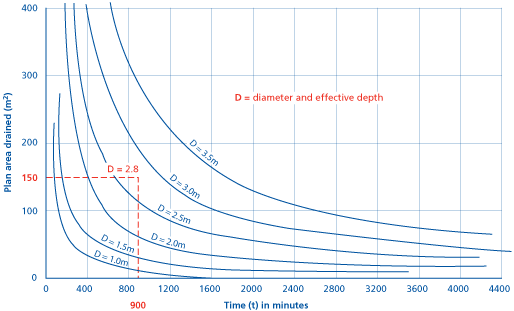
The relationship between the diameter or effective depth required for a soakaway to suit a given area of roof and/or paved area, and the average time (t) given by the test outlined on the previous page, is shown on the graph below. The diameter and effective depth below invert level are assumed to be the same dimension (D).

EXAMPLE
| Test time (t) | = 900 minutes |
| Plan area to drain | = 150m2 |
Therefore, using the graph, the diameter and effective depth of the soakaway (D) are both 2.8m.
Notes
- If the ground is of low permeability, dig separate soakaways to drain smaller but distinct parts, for example:
- one side of a roof to one soakaway
- the other side to a second soakaway
- the driveway or yard to a third soakaway.
- Where the permeability of the ground increases with depth, tests in the deepened trial holes will give shorter percolation times, so it may be cheaper to build a smaller soakaway at a greater depth below the surface.
- Where possible, soakaways should be built on land lower than, or sloping away from, buildings. They should also be kept a "safe" distance away from buildings. This should be at least 5m from building foundations. In chalk and other soil and fill material subject to modification or instability, the advice of a specialist geotechnologist should be sought regarding the siting and advisability of soakaways.


